
Regelventil auslegen: Kvs-Wert, Nennweite und Ventilautorität — so wird das Stellglied richtig dimensioniert
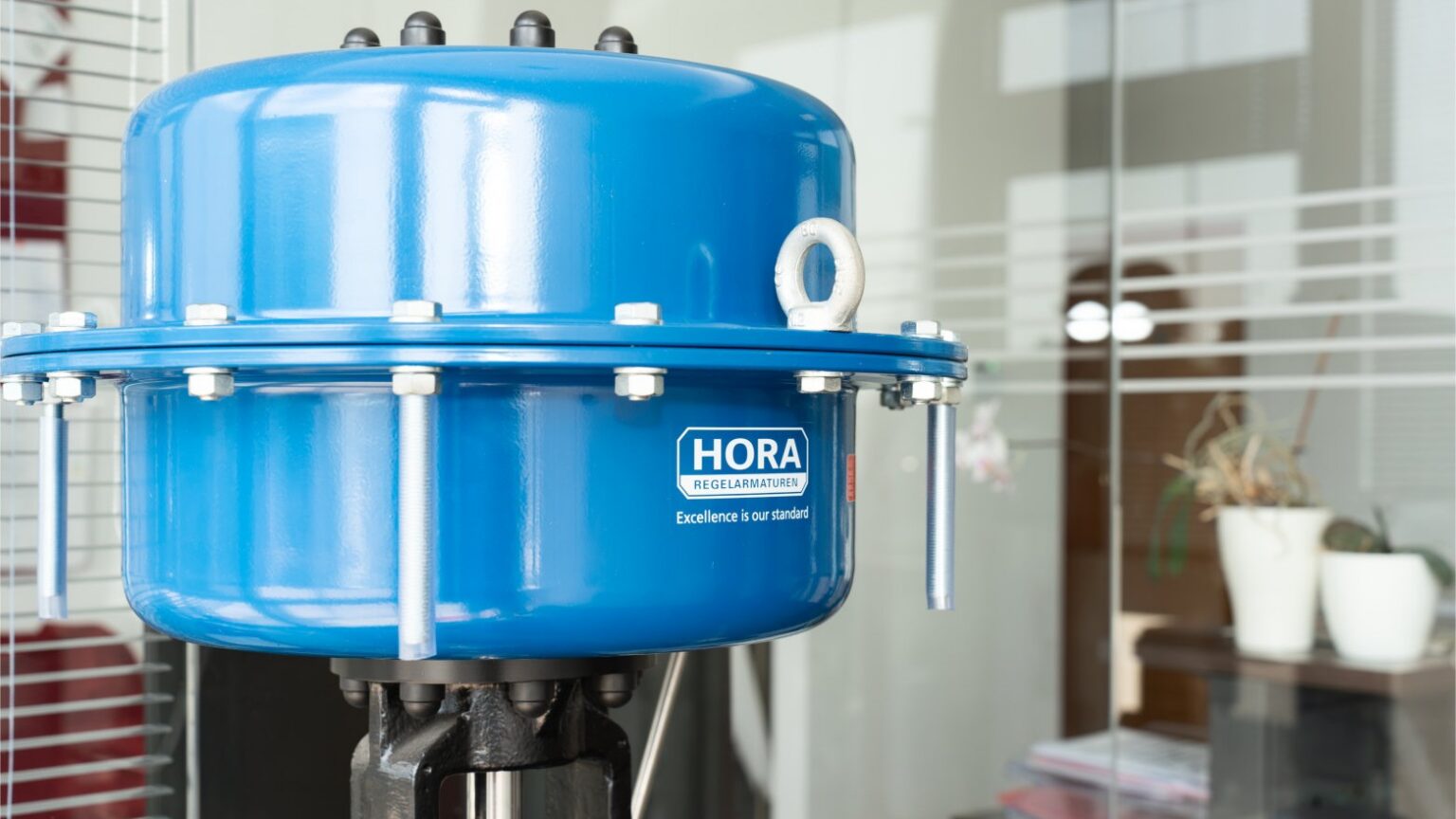
Ein Regelventil richtig zu dimensionieren heißt, drei Dinge zusammenzubringen: den Durchfluss, den die Anlage braucht, den Druck, den das Ventil dafür verbrauchen darf, und die Größe des Stellglieds, die beides abbildet. Wer ein Regelventil auslegen muss, landet deshalb fast immer bei denselben Begriffen: Kv-Wert, Kvs-Wert, Ventilautorität und Nennweite. Dieser Beitrag zeigt, wie die vier zusammenhängen, mit welchen Formeln Planer und Instandhalter rechnen und wo die typischen Fehler liegen – allen voran das überdimensionierte Ventil, das im Betrieb kaum aufmacht.
Warum die Auslegung über den Kvs-Wert läuft
Der Kv-Wert beschreibt den Durchfluss eines Ventils in einem genormten Bezugsfall: Er gibt an, wie viele Kubikmeter Wasser pro Stunde bei einem Druckverlust von 1 bar durch das Ventil fließen, bei einer Wassertemperatur zwischen 5 und 30 °C. Der Kvs-Wert ist derselbe Kennwert bei Nennhub, also bei ganz geöffnetem Ventil. Er steht im Datenblatt jeder Baureihe und ist die Größe, nach der ein Regelventil ausgewählt wird.
Wichtig ist die Unterscheidung: Der Kv-Wert ist eine Betriebsgröße, die Sie aus Ihren Anlagendaten berechnen. Der Kvs-Wert ist eine Eigenschaft des Ventils. Die Auslegung besteht darin, zum berechneten Kv-Bedarf einen passenden Kvs-Wert zu finden – nicht zu knapp, damit der Maximaldurchfluss erreicht wird, und nicht zu groß, damit das Ventil im Normalbetrieb noch regelt.
In Datenblättern nach US-Regelwerk steht statt Kv häufig der Cv-Wert (US-Gallonen pro Minute bei 1 psi Druckverlust). Die Umrechnung lautet Cv ≈ 1,156 × Kv. Liegt ein Angebot nach ASME vor, lohnt sich ein kurzer Blick, welcher der beiden Werte gemeint ist – der Unterschied von rund 16 Prozent reicht, um eine Kvs-Stufe zu verfehlen.
Den Kv-Wert berechnen: Flüssigkeit, Dampf und Gas
Für die überschlägige Auslegung genügen die vereinfachten Formeln aus der Praxis. Die vollständigen Gleichungen samt Korrekturfaktoren für Reduzierstücke, Reynoldszahl und Druckverhältnis stehen in der EN 60534-2-1 (IEC 60534-2-1); die Auslegungsprogramme der Hersteller rechnen danach.
Flüssigkeiten: Kv = Q × √(ρ / (1000 × Δp)), mit dem Volumenstrom Q in m³/h, der Dichte ρ in kg/m³ und dem Druckverlust Δp über dem Ventil in bar. Für Wasser vereinfacht sich das zu Kv = Q / √Δp.
Ein Rechenbeispiel: Ein Heizwasserkreis braucht maximal 20 m³/h, über dem Ventil stehen bei diesem Durchfluss 1 bar zur Verfügung. Der Kv-Bedarf ist 20 / √1 = 20 m³/h. Stünden nur 0,5 bar zur Verfügung, wären es bereits 20 / 0,71 ≈ 28 m³/h. Der verfügbare Differenzdruck wirkt also unmittelbar auf die Ventilgröße – und er ist deshalb die Zahl, die in einer Anfrage am häufigsten fehlt oder geschätzt wird.
Dampf: Für Sattdampf und überhitzten Dampf im unterkritischen Bereich gilt näherungsweise Kv = W / 31,6 × √(v₂ / Δp), mit dem Massenstrom W in kg/h und dem spezifischen Volumen v₂ in m³/kg beim Druck nach dem Ventil. Wird der Druckabfall größer als etwa die Hälfte des absoluten Vordrucks, ist die Strömung kritisch: Der Durchfluss steigt dann nicht mehr, wenn der Nachdruck weiter sinkt. Gerechnet wird in diesem Fall mit Δp = p₁/2 und dem spezifischen Volumen bei p₁/2.
Gase: Hier fließen Normvolumenstrom, Normdichte, Temperatur und Druckverhältnis in die Rechnung ein. Auch bei Gasen gibt es den kritischen Bereich, ab dem der Durchfluss nur noch vom Vordruck abhängt. Für Erdgas, Luft oder Wasserstoff empfiehlt sich die Rechnung nach Norm oder über das Auslegungsprogramm des Herstellers.
Vom Kv-Wert zum Kvs-Wert: der Zuschlag
Den berechneten Kv-Wert für den maximalen Durchfluss setzt man nicht eins zu eins als Kvs ein. In der Praxis üblich ist ein Zuschlag von rund 20 bis 30 Prozent: Kvs ≈ 1,2 bis 1,3 × Kv(max). Er deckt Unsicherheiten in den Anlagendaten und Fertigungstoleranzen ab und sorgt dafür, dass das Ventil den Maximaldurchfluss nicht erst ganz am Ende des Hubs erreicht.
Kvs-Werte sind in Stufen erhältlich, meist nach einer geometrischen Reihe wie 1 – 1,6 – 2,5 – 4 – 6,3 – 10 – 16 – 25 – 40 – 63 – 100. Im Beispiel oben ergibt 1,25 × 20 = 25 – die Stufe Kvs 25 passt genau. Liegt das Ergebnis zwischen zwei Stufen, wird in der Regel die nächstgrößere gewählt, sofern der Minimaldurchfluss dann noch regelbar bleibt.
Genau hier beginnt das häufigste Problem: Zuschläge addieren sich. Der Planer rechnet mit Reserve beim Durchfluss, der Anlagenerrichter gibt noch etwas dazu, beim Ventil wird aufgerundet. Am Ende arbeitet das Regelventil im Normalbetrieb bei 10 oder 15 Prozent Hub. Die Folgen kennt jeder Instandhalter: Der Regelkreis schwingt, kleine Hubänderungen bewirken große Durchflussänderungen, und der Kegel arbeitet dicht am Sitz, wo hohe Strömungsgeschwindigkeiten Sitz und Kegel angreifen. Ein Zuschlag gehört deshalb an genau eine Stelle der Rechnung, nicht an jede.
Zur Kontrolle prüft man auch den kleinsten Betriebspunkt: Das Verhältnis von Kv(max) zu Kv(min) muss innerhalb des Stellverhältnisses der gewählten Baureihe liegen. Wie die Ventilkennlinie diese Rechnung beeinflusst, erklärt der Beitrag Regelventil-Kennlinie: linear oder gleichprozentig.
Ventilautorität: wie viel Druckverlust das Ventil haben muss
Die Ventilautorität beschreibt, welchen Anteil am Druckverlust eines Kreises das Regelventil selbst trägt: a = Δp(V100) / (Δp(V100) + Δp(Rest)). Δp(V100) ist der Druckverlust über dem ganz geöffneten Ventil beim Auslegungsdurchfluss, Δp(Rest) der Druckverlust aller übrigen Teile des Kreises mit veränderlichem Durchfluss – Rohrleitung, Wärmetauscher, Armaturen.
Die Autorität entscheidet darüber, ob die Kennlinie aus dem Datenblatt auch in der Anlage ankommt. Bei kleiner Autorität fällt der größte Teil des Drucks in der Anlage ab, solange das Ventil weit offen ist; beim Schließen wandert der Differenzdruck auf das Ventil. Die Betriebskennlinie verformt sich: Ein Ventil mit linearer Kennlinie verhält sich dann fast wie ein Auf-Zu-Ventil, der Großteil der Durchflussänderung passiert auf den ersten Prozent Hub.
Als Richtwert gilt in der Heizungs- und Anlagentechnik eine Autorität von mindestens 0,3, besser 0,5. Im Beispiel: Stehen über dem Ventil 1 bar und fallen im restlichen Kreis 1,5 bar ab, ergibt sich a = 1 / (1 + 1,5) = 0,4. Wird dasselbe Ventil eine Kvs-Stufe größer gewählt und hat dann nur noch 0,3 bar Druckverlust, sinkt die Autorität auf 0,3 / 1,8 ≈ 0,17 – und dieselbe Anlage regelt deutlich schlechter.
Eine hohe Autorität verlangt mehr Förderhöhe von der Pumpe. Diese Abwägung gehört in die Planung: Der Druckverlust über dem Regelventil ist kein Verlust, den man wegoptimiert, sondern die Voraussetzung dafür, dass das Ventil überhaupt regeln kann.
Nennweite: warum das Regelventil oft kleiner ist als die Leitung
Die Nennweite folgt aus dem Kvs-Wert, nicht aus der Rohrleitung. Jede Baureihe bietet je Nennweite einen oder mehrere Kvs-Werte, oft auch reduzierte Garnituren in einem größeren Gehäuse. Ein Regelventil DN 50 in einer Leitung DN 80 ist deshalb kein Fehler, sondern häufig das Ergebnis einer sauberen Auslegung. Den Übergang bilden Reduzierstücke; die Norm berücksichtigt deren Einfluss mit einem eigenen Korrekturfaktor.
Zwei Gegenproben gehören trotzdem dazu. Erstens die Austrittsgeschwindigkeit: Bei Flüssigkeiten liegen übliche Richtwerte im Bereich weniger Meter pro Sekunde, bei Dampf und Gasen deutlich höher; mit steigender Geschwindigkeit nehmen Geräusch und Verschleiß zu. Bei Dampf mit großem Druckabfall vergrößert sich das Volumen nach dem Ventil stark – hier ist oft der Austritt die engste Stelle der Auslegung, nicht der Sitz. Zweitens Druckstufe und Werkstoff: Die Nennweite allein sagt nichts darüber, ob das Gehäuse zu Druck und Temperatur der Anlage passt.
Das Programm von Ing. Wilhelm Friedrich Gesellschaft m. b. H. umfasst Regelventile von DN 15 bis DN 600 in den Druckstufen PN 10 bis PN 630, nach EN und ASME, mit Gehäusen aus EN-GJL-250, P250GH, GP240GH+N, 13CrMo4-4, G17CrMo5-5 sowie Edelstahl, mit Flanschen, Anschweißenden oder Gewinde. Für sehr große Nennweiten und kleine Differenzdrücke, etwa in Luft- und Rauchgaskanälen, ist eine Regelklappe oft das passendere Stellglied; Drossel- und Regelklappen gibt es bis DN 3000. Wann welches Stellglied passt, behandelt der Beitrag Regelklappe oder Regelventil.
Kavitation, Geräusch und Antriebskraft prüfen
Mit Kvs-Wert und Nennweite ist die Auslegung nicht abgeschlossen. Drei Punkte entscheiden darüber, ob das Ventil im Betrieb ruhig arbeitet.
Kavitation bei Flüssigkeiten: Sinkt der Druck an der engsten Stelle unter den Dampfdruck des Mediums, bilden sich Dampfblasen, die danach schlagartig zusammenfallen. Das ist hörbar und greift Kegel, Sitz und Gehäuse an. Gefährdet sind vor allem heiße Medien wie Speisewasser und große Differenzdrücke. Abhilfe schaffen mehrstufige Garnituren, Kaskaden-Regelventile oder eine Aufteilung des Druckabfalls auf mehrere Stellen.
Geräusch bei Dampf und Gasen: Hohe Druckabfälle erzeugen Strömungsgeräusch, das sich vor allem über die Rohrleitung fortpflanzt. Neben geräuscharmen Garnituren gibt es Regelventile mit nachgeschaltetem Silencer.
Antrieb: Der Antrieb muss das Ventil gegen den größten auftretenden Differenzdruck sicher schließen. Das ist meist der Zustand bei geschlossenem Ventil und voller Pumpen- oder Kesselleistung, nicht der Auslegungspunkt. Dazu kommt die Frage der Sicherheitsstellung: Muss das Ventil bei Ausfall der Hilfsenergie öffnen, schließen oder in seiner Stellung bleiben? Pneumatische Antriebe lösen das über Federrückstellung, elektrische über Fail-Safe-Funktionen, etwa mit hydraulischem Schnellschluss oder Akku-Pack. Ein digitaler Stellungsregler verbessert die Positioniergenauigkeit und liefert Diagnosedaten.
Regelventil auslegen in der Praxis: was in Ihre Anfrage gehört
Ob Sie selbst rechnen oder die Auslegung dem Lieferanten überlassen: Die Qualität des Ergebnisses hängt an den Eingangsdaten. Für eine belastbare Auslegung braucht es:
- Medium und Zustand: Wasser, Dampf (Sattdampf oder überhitzt), Gas, Öl; Dichte bzw. spezifisches Volumen, bei Bedarf Viskosität
- Durchfluss in drei Punkten: minimal, normal, maximal
- Vordruck und Nachdruck für jeden dieser drei Punkte, nicht nur einmal
- Betriebs- und Auslegungstemperatur sowie Auslegungsdruck
- Rohrleitungsnennweite, Anschlussart (Flansch, Anschweißenden, Gewinde) und Regelwerk (EN oder ASME)
- Antriebsart, verfügbare Hilfsenergie und gewünschte Sicherheitsstellung
- größter Differenzdruck bei geschlossenem Ventil und geforderte Leckrate am Sitz
Der dritte Punkt wird am häufigsten unterschätzt. Ist nur der Auslegungspunkt bekannt, lässt sich weder die Autorität noch der Regelbereich prüfen. Gerade bei Kreisen mit drehzahlgeregelter Pumpe oder bei Dampfnetzen mit schwankendem Vordruck verschieben sich die Drücke über den Lastbereich erheblich.
Auf Basis dieser Daten legt Ing. Wilhelm Friedrich Gesellschaft m. b. H. das Ventil mit den vertretenen Herstellern aus, darunter RTK Regeltechnik und HORA Holter Regelarmaturen. Welche RTK-Baureihe wofür passt, steht im Beitrag RTK Regelventile: MV 5200, MV 5300, MV 5400 oder MV 5900. Die eigene Serviceabteilung übernimmt auf Wunsch die Inbetriebnahme vor Ort, in Österreich und im Servicegebiet Tschechien, Slowakei, Ungarn, Slowenien und Italien (Service).
Häufige Fragen
Wie berechne ich den Kvs-Wert eines Regelventils?
Zuerst den Kv-Wert für den maximalen Durchfluss berechnen, bei Wasser Kv = Q / √Δp. Dieses Ergebnis mit 1,2 bis 1,3 multiplizieren und die nächstpassende Kvs-Stufe der Baureihe wählen. Danach prüfen, ob der kleinste Betriebspunkt im Stellverhältnis bleibt.
Was passiert, wenn das Regelventil zu groß ist?
Das Ventil arbeitet im Normalbetrieb mit sehr kleinem Hub. Der Regelkreis wird unruhig oder schwingt, die Regelgenauigkeit sinkt, und die hohe Strömungsgeschwindigkeit nahe am Sitz greift Sitz und Kegel an. Ein überdimensioniertes Ventil ist deshalb keine Reserve, sondern ein Regelproblem.
Welche Ventilautorität ist richtig?
Als Richtwert mindestens 0,3, besser um 0,5. Höhere Werte verbessern das Regelverhalten, verlangen aber mehr Förderhöhe. Bei Dampf- und Prozessanwendungen ergibt sich der Druckverlust meist aus dem Prozess selbst, dort steht die Prüfung auf kritische Strömung, Kavitation und Geräusch im Vordergrund.
Muss das Regelventil dieselbe Nennweite haben wie die Rohrleitung?
Nein. Die Nennweite ergibt sich aus dem Kvs-Wert. Ein Regelventil ist häufig ein bis zwei Nennweiten kleiner als die Leitung und wird über Reduzierstücke eingebunden. Zu prüfen bleiben Austrittsgeschwindigkeit, Druckstufe und Werkstoff.
Fazit: erst rechnen, dann einmal aufrunden
Wer ein Regelventil auslegen will, braucht drei Betriebspunkte mit Durchfluss und Drücken, rechnet daraus den Kv-Wert, schlägt einmal 20 bis 30 Prozent auf und prüft danach Autorität, Nennweite, Kavitation und Antriebskraft. Die Ausführungen von DN 15 bis DN 600 zeigt die Seite Regelventile. Für die Auslegung im konkreten Fall ist Ing. Wilhelm Friedrich Gesellschaft m. b. H. in Stetten seit 1983 Ihr Ansprechpartner in Österreich.
Sizing a control valve: Kvs value, nominal size and valve authority – how to dimension the final control element
Sizing a control valve correctly means bringing three things together: the flow rate the plant needs, the pressure the valve is allowed to consume for it, and the size of the final control element that reflects both. Anyone who has to size a control valve therefore ends up with the same terms almost every time: Kv value, Kvs value, valve authority and nominal size. This article shows how the four are connected, which formulas planners and maintenance engineers use, and where the typical mistakes lie – above all the oversized valve that barely opens in operation.
Why sizing is based on the Kvs value
The Kv value describes the flow through a valve under a standardised reference condition: it states how many cubic metres of water per hour flow through the valve at a pressure drop of 1 bar, at a water temperature between 5 and 30 °C. The Kvs value is the same figure at rated travel, i.e. with the valve fully open. It is listed in the data sheet of every series and is the figure by which a control valve is selected.
The distinction matters: the Kv value is an operating figure that you calculate from your plant data. The Kvs value is a property of the valve. Sizing means finding a Kvs value that matches the calculated Kv requirement – not too tight, so that the maximum flow is reached, and not too large, so that the valve still controls in normal operation.
Data sheets following US codes often state the Cv value instead of Kv (US gallons per minute at 1 psi pressure drop). The conversion is Cv ≈ 1.156 × Kv. If an offer is based on ASME, it is worth checking which of the two values is meant – the difference of around 16 percent is enough to miss a Kvs step.
Calculating the Kv value: liquids, steam and gas
For a first sizing, the simplified formulas used in practice are sufficient. The complete equations including correction factors for reducers, Reynolds number and pressure ratio are given in EN 60534-2-1 (IEC 60534-2-1); manufacturers‘ sizing programs calculate on that basis.
Liquids: Kv = Q × √(ρ / (1000 × Δp)), with the volume flow Q in m³/h, the density ρ in kg/m³ and the pressure drop Δp across the valve in bar. For water this simplifies to Kv = Q / √Δp.
A worked example: a heating water circuit needs a maximum of 20 m³/h, and 1 bar is available across the valve at this flow rate. The Kv requirement is 20 / √1 = 20 m³/h. If only 0.5 bar were available, it would already be 20 / 0.71 ≈ 28 m³/h. The available differential pressure therefore has a direct effect on valve size – which is why it is the figure most often missing or estimated in an enquiry.
Steam: For saturated and superheated steam in the subcritical range, approximately Kv = W / 31.6 × √(v₂ / Δp), with the mass flow W in kg/h and the specific volume v₂ in m³/kg at the pressure downstream of the valve. If the pressure drop exceeds roughly half of the absolute inlet pressure, the flow becomes critical: the flow rate no longer increases when the outlet pressure falls further. In that case the calculation uses Δp = p₁/2 and the specific volume at p₁/2.
Gases: Here the standard volume flow, standard density, temperature and pressure ratio enter the calculation. Gases also have a critical range beyond which the flow depends only on the inlet pressure. For natural gas, air or hydrogen, calculation according to the standard or with the manufacturer’s sizing program is recommended.
From Kv to Kvs: the margin
The Kv value calculated for maximum flow is not used one-to-one as the Kvs. A margin of around 20 to 30 percent is common practice: Kvs ≈ 1.2 to 1.3 × Kv(max). It covers uncertainties in the plant data and manufacturing tolerances and ensures that the valve does not reach maximum flow only at the very end of its travel.
Kvs values are available in steps, usually following a geometric series such as 1 – 1.6 – 2.5 – 4 – 6.3 – 10 – 16 – 25 – 40 – 63 – 100. In the example above, 1.25 × 20 = 25 – the Kvs 25 step fits exactly. If the result falls between two steps, the next larger one is usually chosen, provided the minimum flow can still be controlled.
This is exactly where the most common problem begins: margins add up. The planner adds a reserve to the flow rate, the plant contractor adds a little more, and the valve is rounded up. In the end the control valve operates at 10 or 15 percent travel in normal operation. Every maintenance engineer knows the consequences: the control loop oscillates, small changes in travel cause large changes in flow, and the plug works close to the seat, where high flow velocities attack seat and plug. A margin therefore belongs in exactly one place in the calculation, not in every one.
As a check, the lowest operating point is also examined: the ratio of Kv(max) to Kv(min) must lie within the rangeability of the selected series. How the valve characteristic influences this calculation is explained in the article control valve characteristic: linear or equal percentage (German).
Valve authority: how much pressure drop the valve needs
Valve authority describes the share of a circuit’s pressure drop that is taken by the control valve itself: a = Δp(V100) / (Δp(V100) + Δp(rest)). Δp(V100) is the pressure drop across the fully open valve at design flow, Δp(rest) is the pressure drop of all other parts of the circuit with variable flow – piping, heat exchangers, fittings.
Authority decides whether the characteristic shown in the data sheet actually reaches the plant. With low authority, most of the pressure is lost in the plant while the valve is wide open; as the valve closes, the differential pressure shifts onto the valve. The installed characteristic becomes distorted: a valve with a linear characteristic then behaves almost like an on-off valve, with most of the change in flow happening in the first few percent of travel.
As a guideline in heating and plant engineering, an authority of at least 0.3, preferably 0.5, applies. In the example: if 1 bar is available across the valve and 1.5 bar is lost in the rest of the circuit, a = 1 / (1 + 1.5) = 0.4. If the same valve is selected one Kvs step larger and then only has a pressure drop of 0.3 bar, the authority falls to 0.3 / 1.8 ≈ 0.17 – and the same plant controls considerably worse.
High authority requires more pump head. This trade-off belongs in the design stage: the pressure drop across the control valve is not a loss to be optimised away, but the precondition for the valve to control at all.
Nominal size: why the control valve is often smaller than the pipe
The nominal size follows from the Kvs value, not from the pipe. Every series offers one or more Kvs values per nominal size, often also reduced trims in a larger body. A DN 50 control valve in a DN 80 line is therefore not a mistake, but often the result of careful sizing. Reducers form the transition; the standard accounts for their influence with a separate correction factor.
Two cross-checks are still part of the job. First, the outlet velocity: for liquids, common guideline values are in the range of a few metres per second, for steam and gases considerably higher; noise and wear increase with velocity. With steam and a large pressure drop, the volume downstream of the valve increases considerably – here the outlet is often the narrowest point of the sizing, not the seat. Second, pressure rating and material: the nominal size alone says nothing about whether the body suits the pressure and temperature of the plant.
The range of Ing. Wilhelm Friedrich Gesellschaft m. b. H. covers control valves from DN 15 to DN 600 in pressure ratings PN 10 to PN 630, to EN and ASME, with bodies in EN-GJL-250, P250GH, GP240GH+N, 13CrMo4-4, G17CrMo5-5 and stainless steel, with flanges, butt-weld ends or threads. For very large nominal sizes and low differential pressures, for example in air and flue gas ducts, a control damper is often the more suitable final control element; throttle and control dampers are available up to DN 3000. Which final control element suits which task is covered in the article control damper or control valve (German).
Checking cavitation, noise and actuator force
Kvs value and nominal size do not complete the sizing. Three points decide whether the valve operates smoothly.
Cavitation with liquids: if the pressure at the narrowest point drops below the vapour pressure of the medium, vapour bubbles form and then collapse abruptly. This is audible and attacks plug, seat and body. Hot media such as feedwater and large differential pressures are particularly at risk. Remedies are multi-stage trims, cascade control valves or splitting the pressure drop across several points.
Noise with steam and gases: high pressure drops create flow noise that travels mainly along the pipe. In addition to low-noise trims, there are control valves with a downstream silencer.
Actuator: the actuator must close the valve reliably against the highest differential pressure that occurs. This is usually the condition with the valve closed and full pump or boiler output, not the design point. Then there is the question of the fail-safe position: should the valve open, close or stay in position if the auxiliary power fails? Pneumatic actuators solve this with spring return, electric actuators with fail-safe functions, for example with hydraulic quick closing or a battery pack. A digital positioner improves positioning accuracy and provides diagnostic data.
Sizing a control valve in practice: what belongs in your enquiry
Whether you calculate yourself or leave the sizing to the supplier: the quality of the result depends on the input data. A reliable sizing needs:
- medium and condition: water, steam (saturated or superheated), gas, oil; density or specific volume, viscosity if required
- flow rate at three points: minimum, normal, maximum
- inlet and outlet pressure for each of these three points, not just once
- operating and design temperature as well as design pressure
- pipe nominal size, connection type (flange, butt-weld ends, thread) and code (EN or ASME)
- actuator type, available auxiliary power and required fail-safe position
- highest differential pressure with the valve closed and required seat leakage rate
The third point is the one most often underestimated. If only the design point is known, neither authority nor control range can be checked. Especially in circuits with speed-controlled pumps or in steam networks with fluctuating inlet pressure, the pressures shift considerably across the load range.
Based on this data, Ing. Wilhelm Friedrich Gesellschaft m. b. H. sizes the valve with the manufacturers it represents, including RTK Regeltechnik and HORA Holter Regelarmaturen. Which RTK series suits which task is described in the article RTK control valves: MV 5200, MV 5300, MV 5400 or MV 5900 (German). On request, the company’s own service department carries out commissioning on site, in Austria and in the service area of Czechia, Slovakia, Hungary, Slovenia and Italy (service).
Frequently asked questions
How do I calculate the Kvs value of a control valve?
First calculate the Kv value for maximum flow, for water Kv = Q / √Δp. Multiply this result by 1.2 to 1.3 and select the closest suitable Kvs step of the series. Then check whether the lowest operating point stays within the rangeability.
What happens if the control valve is too large?
The valve operates with very small travel in normal operation. The control loop becomes unstable or oscillates, control accuracy drops, and the high flow velocity close to the seat attacks seat and plug. An oversized valve is therefore not a reserve, but a control problem.
What is the right valve authority?
As a guideline at least 0.3, preferably around 0.5. Higher values improve control behaviour but require more pump head. In steam and process applications, the pressure drop usually results from the process itself; there, the check for critical flow, cavitation and noise comes first.
Does the control valve have to have the same nominal size as the pipe?
No. The nominal size results from the Kvs value. A control valve is often one or two nominal sizes smaller than the pipe and is connected via reducers. Outlet velocity, pressure rating and material still need to be checked.
Conclusion: calculate first, then round up once
Anyone sizing a control valve needs three operating points with flow and pressures, calculates the Kv value from them, adds 20 to 30 percent once and then checks authority, nominal size, cavitation and actuator force. The designs from DN 15 to DN 600 are shown on the page control valves. For sizing in a specific case, Ing. Wilhelm Friedrich Gesellschaft m. b. H. in Stetten has been your contact in Austria since 1983.
