
Absperrklappe auswählen: Bauform, Dichtung, Anschluss und Antrieb — die Entscheidung in der richtigen Reihenfolge
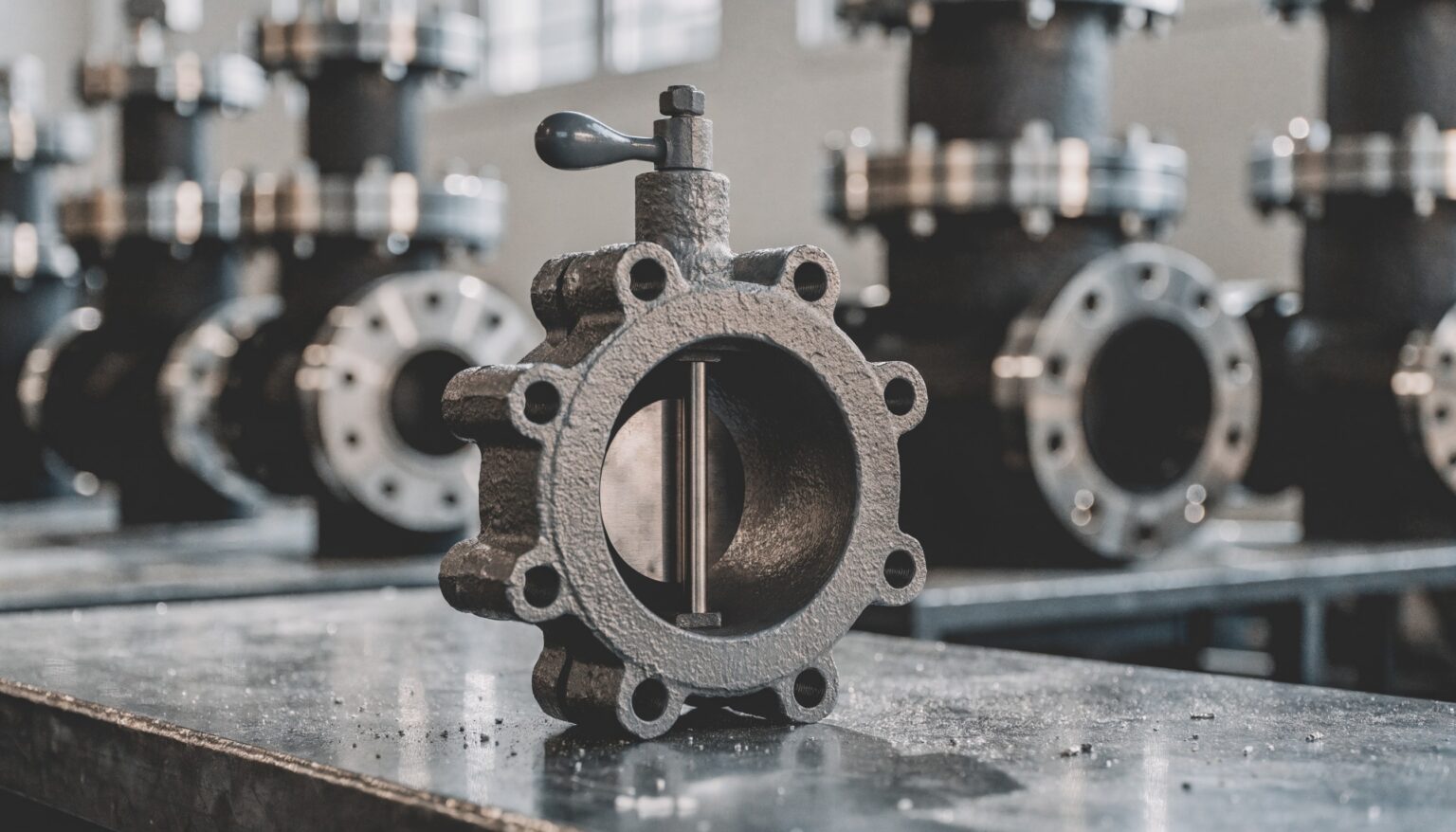
Wer eine Absperrklappe anfragt, schreibt meist zuerst Nennweite und Antrieb hin – und merkt erst beim Angebot, dass Dichtung oder Bauform nicht zum Medium passen. Die Auswahl einer Absperrklappe ist eine Kette von Entscheidungen, in der jede Stufe die nächste einschränkt: Medium, Druck und Temperatur legen die Bauform fest, die Bauform begrenzt die Dichtung, Dichtung und Einbauort bestimmen die Anschlussart, und erst am Ende steht der Antrieb. Dieser Leitfaden zeigt die Reihenfolge, nennt die Abhängigkeiten zwischen den Stufen und verweist bei jeder Stufe auf den Beitrag, der sie im Detail behandelt.
Warum die Reihenfolge bei der Absperrklappe zählt
Eine Absperrklappe ist eine Armatur mit Vierteldrehung: Die Scheibe sitzt dauerhaft im Strömungsweg und wird zum Öffnen um 90 Grad gedreht. Daraus ergeben sich ihre Stärken – kurze Baulänge, geringes Gewicht, große Nennweiten bei vertretbarem Aufwand – und ihre Grenzen. Fehler entstehen fast immer dann, wenn eine spätere Entscheidung vor einer früheren getroffen wird. Ein typisches Beispiel: Eine weichdichtende Zwischenflanschklappe mit Pneumatikantrieb hat sich im Kühlwasserkreis bewährt und wird deshalb auch für eine Heißwasserleitung bestellt. Dort ist die Elastomermanschette überfordert, die Dichtheit lässt nach, und wird später auf eine exzentrische Bauform gewechselt, passt der Antrieb nicht mehr zum höheren Losbrechmoment.
Ing. Wilhelm Friedrich Gesellschaft m. b. H. liefert Absperrklappen von DN 65 bis DN 2500 in den Druckstufen PN 10 bis PN 160, nach EN und ASME. Bei dieser Bandbreite ist die Frage selten, ob es eine passende Klappe gibt, sondern welche Angaben nötig sind, um sie eindeutig zu spezifizieren. Die folgenden sechs Schritte sind genau diese Angaben – in der Reihenfolge, in der sie voneinander abhängen.
Schritt 1: Medium, Druck und Temperatur festlegen
Alles beginnt beim Betriebszustand, und zwar nicht nur beim Normalbetrieb, sondern bei den Grenzwerten. Für die Auswahl zählen:
- Medium und Zustand: Wasser, Kühlwasser, Heißwasser, Sattdampf, Heißdampf, Thermalöl, Gas, Luft, Schlamm oder Medien mit Feststoffanteil.
- Betriebs- und Auslegungsdruck sowie der größte Differenzdruck, gegen den die Klappe öffnen und schließen muss.
- Betriebs- und Auslegungstemperatur, einschließlich der Spitzen beim Anfahren, Spülen oder Ausblasen.
- Funktion: reines Auf-Zu, gelegentliches Drosseln oder dauerhaftes Regeln, dazu die erwartete Zahl der Schaltspiele.
Aus diesen Werten ergeben sich Druckstufe und Gehäusewerkstoff. Für Wasser im Niederdruckbereich genügt oft Grauguss EN-GJL-250. Für Dampf und höhere Temperaturen kommen Stahlguss und Stahl wie GP240GH+N oder P250GH in Frage, bei hohen Temperaturen warmfeste Werkstoffe wie 13CrMo4-4 oder G17CrMo5-5, bei korrosiven Medien Edelstahl. Ein Punkt, der in Anfragen häufig fehlt, ist der Differenzdruck beim Öffnen. Er bestimmt später das Losbrechmoment und damit die Antriebsgröße. Wer ihn hier nicht festhält, muss ihn in Schritt 5 nachreichen.
Schritt 2: Bauform wählen – zentrisch, doppelexzentrisch oder dreifach exzentrisch
Die Bauform beschreibt, wie Welle und Scheibe zur Dichtfläche liegen. Sie ist die wichtigste Einzelentscheidung, weil sie festlegt, welche Dichtungen überhaupt möglich sind.
Zentrische Absperrklappe: Die Welle läuft mittig durch die Scheibe, die Scheibe dichtet über ihren ganzen Umfang gegen eine elastische Manschette. Die Bauform ist einfach, kompakt und wirtschaftlich. Sie passt zu Wasser, Kühlwasser, Luft und vielen Medien der Wasser- und Abwassertechnik bei niedrigen Drücken und bei Temperaturen, die das Elastomer verträgt. Weil die Scheibe beim Schließen über die Manschette reibt, ist sie für Dampf und hohe Temperaturen nicht vorgesehen.
Doppelexzentrische Absperrklappe: Die Welle sitzt hinter der Dichtebene und zusätzlich seitlich aus der Rohrmitte versetzt. Beim Öffnen hebt die Scheibe nach wenigen Grad vom Sitz ab, die Reibung beschränkt sich auf den letzten Teil des Schließwegs. Das schont die Dichtung und erlaubt höhere Drücke und Temperaturen. Doppelexzentrische Klappen gibt es mit weichem Sitz, etwa aus PTFE, oder metallisch dichtend.
Dreifach exzentrische Absperrklappe: Zu den beiden Versätzen kommt ein schräg gestellter, kegeliger Dichtsitz. Die Scheibe berührt den Sitz erst in der Endlage und schließt praktisch reibungsfrei. Diese Bauform ist metallisch dichtend und wird für Dampf, Heißwasser, Thermalöl und hohe Temperaturen eingesetzt – also dort, wo im Kraftwerks- und Anlagenbau früher oft ein Schieber stand. Im Programm von Ing. Wilhelm Friedrich Gesellschaft m. b. H. gibt es darüber hinaus vierfach exzentrische Sonderausführungen.
Als Faustregel gilt: Je heißer das Medium und je höher die Anforderung an die Dichtheit bei Temperatur, desto mehr Exzentrizität. Die lieferbaren Ausführungen finden Sie auf der Seite Absperrklappen.
Schritt 3: Dichtung – weichdichtend oder metallisch dichtend
Mit der Bauform ist der Spielraum für die Dichtung schon eingegrenzt. Weichdichtende Klappen mit Elastomer- oder PTFE-Sitz erreichen eine hohe Dichtheit bei niedrigen Schließmomenten, sind aber durch die Temperatur- und Medienbeständigkeit des Dichtwerkstoffs begrenzt. Metallisch dichtende Klappen sind temperatur- und abrasionsfester, brauchen aber mehr Schließmoment, und ihre Dichtheit hängt stärker von Bauform, Bearbeitung und Antrieb ab.
Benennen Sie in der Anfrage die geforderte Dichtheit, etwa als Leckrate nach EN 12266-1, statt nur „dicht“ zu schreiben, und geben Sie an, ob die Klappe in beide Richtungen absperren muss. Ob weich oder metallisch die richtige Wahl ist, behandelt der Beitrag Weichdichtende Absperrklappen oder metallisch dichtende Bauform im Detail. Ist an einer vorhandenen Klappe die Dichtfläche bereits beschädigt, hilft der Beitrag Riefen an Absperrklappen, Schiebern und Ventilen bei der Frage, ob Nacharbeit oder Tausch sinnvoll ist.
Schritt 4: Anschlussart – Zwischenflansch, Anflansch, Doppelflansch oder Anschweißenden
Die Anschlussart hängt vom Einbauort ab, von der Druckstufe und davon, ob die Leitung einseitig demontiert werden muss.
- Zwischenflansch (Wafer): Die Klappe wird zwischen zwei Rohrflansche gespannt, die Schrauben laufen außen am Gehäuse vorbei. Das ist die kürzeste und leichteste Lösung, aber eine Seite der Leitung lässt sich nicht abnehmen, ohne dass die Klappe frei wird.
- Anflansch (Lug): Das Gehäuse hat Gewindeaugen, jede Seite wird für sich verschraubt. Damit ist die Klappe auch bei einseitig demontierter Leitung oder als Endarmatur einsetzbar, sofern der Hersteller das für den jeweiligen Druck freigibt.
- Doppelflansch: Eigene Flansche am Gehäuse, robust und bei großen Nennweiten und höheren Drücken üblich.
- Anschweißenden: Für hohe Drücke und Temperaturen, etwa in Dampf- und Speisewasserleitungen, wo Flanschverbindungen vermieden werden sollen.
Vor- und Nachteile je Anschlussart samt typischer Montagefehler beschreibt der Beitrag Absperrklappe mit Zwischenflansch, Anflansch oder Doppelflansch.
Schritt 5: Antrieb – Hand, pneumatisch, elektrisch oder hydraulisch
Der Antrieb kommt zuletzt, weil er sich nach allem davor richtet: Bauform und Dichtung bestimmen das Losbrechmoment, der Differenzdruck aus Schritt 1 erhöht es, und die Anschlussart beeinflusst, wie der Antrieb auf die Klappe gesetzt wird. Ein Handhebel oder ein Getriebe mit Handrad genügt bei selten betätigten Armaturen. Pneumatische Antriebe sind schnell und können mit Federrückstellung eine definierte Sicherheitsstellung einnehmen, wenn Druckluft vorhanden ist. Elektrische Antriebe passen dort, wo keine Druckluft verfügbar ist oder eine Einbindung in die Leittechnik mit Stellungsrückmeldung gewünscht ist. Hydraulische Antriebe kommen bei großen Momenten und großen Nennweiten zum Einsatz, etwa im Kraftwerksbereich.
Für die Auslegung zählt nicht das Moment im Normalbetrieb, sondern das größte Moment im ungünstigsten Betriebsfall, dazu eine Reserve. Welcher Antrieb für welchen Einsatz passt, behandelt der Beitrag Absperrklappe mit Antrieb: pneumatisch, elektrisch oder hydraulisch.
Schritt 6: Druckverlust und Einbaulage prüfen
Die Scheibe bleibt auch in Offenstellung im Strömungsweg. Bei kleinen Nennweiten und hohen Strömungsgeschwindigkeiten fällt der Druckverlust deshalb spürbar ins Gewicht, bei großen Nennweiten ist er meist unkritisch. Für die Bewertung gibt der Hersteller den Kv-Wert beziehungsweise den Widerstandsbeiwert der Offenstellung an.
Soll die Klappe nicht nur absperren, sondern dauerhaft drosseln, ist eine reine Absperrklappe meist die falsche Wahl. Im fast geschlossenen Bereich ist die Strömung instabil, die Dichtfläche wird direkt angeströmt und verschleißt. Für Regelaufgaben gibt es eigene Drossel- und Regelklappen.
Bei der Einbaulage sind drei Punkte zu prüfen. Erstens der Abstand zu Krümmern, Pumpen und Reduzierungen: Eine ungleichmäßige Anströmung erhöht Moment und Verschleiß, die Hersteller geben dafür Mindestabstände an. Zweitens die Wellenlage: Bei Medien mit Feststoffen oder Ablagerungen wird die Welle in der Regel waagrecht angeordnet, damit sich im unteren Lager nichts festsetzt. Drittens der Schwenkbereich: Bei Zwischenflansch- und Anflanschklappen ragt die geöffnete Scheibe in die angrenzende Rohrleitung. Bei ausgekleideten Rohren, kleinen Innendurchmessern oder direkt anschließenden Armaturen muss geprüft werden, ob die Scheibe frei schwenken kann.
Absperrklappe oder doch Absperrschieber?
Die Reihenfolge oben setzt voraus, dass die Klappe überhaupt die richtige Armatur ist. Bei großen Nennweiten, begrenztem Platz und kurzen Schaltzeiten spricht viel für die Klappe. Wo ein voller, ungehinderter Querschnitt gebraucht wird oder sehr hohe Druckstufen gefordert sind, bleibt der Absperrschieber eine Option – Ing. Wilhelm Friedrich Gesellschaft m. b. H. liefert Schieber bis PN 630. Die Abwägung im Einzelnen behandelt der Beitrag Absperrklappe oder Absperrschieber: welche Armatur wofür.
Geht es um den Ersatz einer vorhandenen Klappe, deren Fabrikat nicht mehr erhältlich ist, gilt dieselbe Reihenfolge. Baulänge und Anschlussmaße der alten Armatur kommen dann als zusätzliche Randbedingung dazu. Ein Beispiel dafür zeigt der Beitrag Siegwart-Absperrklappe ersetzen.
Diese Angaben braucht eine Anfrage
Aus den sechs Schritten ergibt sich eine kurze Liste. Liegen diese Angaben vor, lässt sich eine Absperrklappe ohne Rückfragen anbieten:
- Medium und Zustand, Betriebs- und Auslegungsdruck, größter Differenzdruck
- Betriebs- und Auslegungstemperatur einschließlich Spitzen
- Nennweite, Druckstufe und Norm (EN oder ASME)
- Funktion (Auf-Zu oder Drosseln) und erwartete Schaltspiele
- geforderte Dichtheit, Durchflussrichtung, Absperrung in eine oder beide Richtungen
- Anschlussart, bei Ersatz die Baulänge der vorhandenen Armatur
- Antriebsart, Steuersignal, Sicherheitsstellung und Stellungsmeldung
- Einbaulage, Wellenlage und Platzverhältnisse
Fehlt eine Angabe, klären wir sie gemeinsam. Die eigene Serviceabteilung von Ing. Wilhelm Friedrich Gesellschaft m. b. H. unterstützt auch bei Inbetriebnahme und Reparatur vor Ort, in Österreich sowie in Tschechien, der Slowakei, Ungarn, Slowenien und Italien. Mehr dazu auf der Seite Service.
Häufige Fragen zur Absperrklappe
Welche Absperrklappe eignet sich für Dampf?
Für Dampf kommt in der Regel eine dreifach exzentrische, metallisch dichtende Absperrklappe in Frage, je nach Druck mit Doppelflansch oder Anschweißenden und mit einem Gehäusewerkstoff, der zur Temperatur passt. Zentrische Klappen mit Elastomermanschette sind dafür nicht vorgesehen.
Kann man mit einer Absperrklappe regeln?
Gelegentliches Drosseln im mittleren Öffnungsbereich ist möglich. Für dauerhaftes Regeln, besonders bei kleinen Öffnungswinkeln, sind Drossel- und Regelklappen die bessere Wahl, weil eine Absperrklappe dort an der Dichtfläche verschleißt.
Was ist der Unterschied zwischen Zwischenflansch und Anflansch?
Die Zwischenflanschklappe wird zwischen zwei Flansche gespannt und hält nur, solange beide Seiten verschraubt sind. Die Anflanschklappe hat Gewindeaugen, jede Seite wird für sich verschraubt. Sie bleibt damit auch bei einseitig abgenommener Leitung an ihrem Platz.
Welche Nennweiten und Druckstufen sind lieferbar?
Ing. Wilhelm Friedrich Gesellschaft m. b. H. liefert Absperrklappen von DN 65 bis DN 2500 in den Druckstufen PN 10 bis PN 160, nach EN und ASME, mit Handbetätigung oder elektrischem, pneumatischem oder hydraulischem Antrieb sowie als Sonderausführung.
Fazit
Eine Absperrklappe wird nicht über den Antrieb oder die Nennweite ausgewählt, sondern über das Medium. Wer die Reihenfolge einhält – Betriebszustand, Bauform, Dichtung, Anschlussart, Antrieb, Druckverlust und Einbaulage –, vermeidet die typischen Fehlgriffe und bekommt ein Angebot, das ohne Nachbesserung passt. Für Planer, Instandhalter und Betriebsleiter in Kraftwerken, Industrie und Anlagenbau ist die Liste der Angaben oben ein guter Ausgangspunkt. Ing. Wilhelm Friedrich Gesellschaft m. b. H. legt mit diesen Daten die passende Absperrklappe aus und begleitet die Armatur mit der eigenen Serviceabteilung bis zur Inbetriebnahme.
Selecting a butterfly valve: design, seal, connection and actuator – the decisions in the right order
When engineers request a butterfly valve, they usually write down the nominal size and the actuator first – and only notice at the quotation stage that the seal or the design does not suit the medium. Selecting a butterfly valve is a chain of decisions in which each step narrows the next: medium, pressure and temperature determine the design, the design limits the seal, seal and installation point determine the connection type, and the actuator comes last. This guide sets out the order, explains how the steps depend on each other and links each step to the article that covers it in detail (in German).
Why the order matters
A butterfly valve is a quarter-turn valve: the disc sits permanently in the flow path and is rotated through 90 degrees to open. This gives it its strengths – short face-to-face length, low weight, large nominal sizes at reasonable cost – and its limits. Mistakes almost always happen when a later decision is made before an earlier one. A typical example: a soft-seated wafer valve with a pneumatic actuator has proven itself in the cooling water circuit and is therefore also ordered for a hot water line. There the elastomer liner is overstretched, tightness deteriorates, and if the valve is later changed to an eccentric design, the actuator no longer matches the higher breakaway torque.
Ing. Wilhelm Friedrich Gesellschaft m. b. H. supplies butterfly valves from DN 65 to DN 2500 in pressure ratings PN 10 to PN 160, to EN and ASME. With this range, the question is rarely whether a suitable valve exists, but which data is needed to specify it unambiguously. The following six steps are exactly that data – in the order in which the items depend on each other.
Step 1: Define medium, pressure and temperature
Everything starts with the operating conditions – not only normal operation, but the limit values. What counts:
- Medium and state: water, cooling water, hot water, saturated steam, superheated steam, thermal oil, gas, air, sludge or media containing solids.
- Operating and design pressure as well as the maximum differential pressure against which the valve must open and close.
- Operating and design temperature, including peaks during start-up, flushing or blow-out.
- Function: pure on-off service, occasional throttling or continuous control, plus the expected number of operating cycles.
These values determine the pressure rating and the body material. For low-pressure water, grey cast iron EN-GJL-250 is often sufficient. For steam and higher temperatures, cast steel and steel such as GP240GH+N or P250GH are options, for high temperatures creep-resistant grades such as 13CrMo4-4 or G17CrMo5-5, and stainless steel for corrosive media. One item often missing from enquiries is the differential pressure at opening. It later determines the breakaway torque and therefore the actuator size. If it is not recorded here, it has to be supplied in step 5.
Step 2: Choose the design – concentric, double offset or triple offset
The design describes how shaft and disc are positioned relative to the sealing surface. It is the most important single decision because it defines which seals are possible at all.
Concentric butterfly valve: the shaft runs through the centre of the disc, and the disc seals around its entire circumference against an elastic liner. The design is simple, compact and economical. It suits water, cooling water, air and many media in water and wastewater engineering at low pressures and at temperatures the elastomer can withstand. Because the disc rubs against the liner when closing, it is not intended for steam or high temperatures.
Double offset butterfly valve: the shaft is positioned behind the sealing plane and additionally offset from the pipe centreline. When opening, the disc lifts off the seat after a few degrees, so friction is limited to the last part of the closing stroke. This protects the seal and allows higher pressures and temperatures. Double offset valves are available with a soft seat, for example PTFE, or metal-seated.
Triple offset butterfly valve: a third offset is added in the form of an inclined, conical seat. The disc only touches the seat in the end position and closes practically without friction. This design is metal-seated and is used for steam, hot water, thermal oil and high temperatures – in other words, where a gate valve used to be the usual choice in power plant and plant engineering. The range of Ing. Wilhelm Friedrich Gesellschaft m. b. H. also includes quadruple offset special designs.
As a rule of thumb: the hotter the medium and the higher the tightness requirement at temperature, the more offset is needed. The available versions are listed on the page Butterfly valves.
Step 3: Seal – soft-seated or metal-seated
Once the design is chosen, the options for the seal are already narrowed down. Soft-seated valves with an elastomer or PTFE seat achieve high tightness at low closing torques, but are limited by the temperature and media resistance of the sealing material. Metal-seated valves withstand higher temperatures and abrasion, but need more closing torque, and their tightness depends more on design, machining and actuator.
State the required tightness in your enquiry, for example as a leakage rate to EN 12266-1, rather than simply writing „tight“, and specify whether the valve has to shut off in one or both directions. Whether soft or metal seating is right is covered in detail in the article Soft-seated or metal-seated butterfly valves. If the sealing surface of an existing valve is already damaged, the article Scoring on butterfly valves, gate valves and globe valves helps decide whether reworking or replacement makes sense.
Step 4: Connection type – wafer, lug, double flange or weld ends
The connection type depends on the installation point, the pressure rating and whether the line has to be dismantled on one side.
- Wafer: the valve is clamped between two pipe flanges, with the bolts running past the outside of the body. This is the shortest and lightest solution, but one side of the line cannot be removed without the valve coming loose.
- Lug: the body has threaded lugs, and each side is bolted separately. The valve can therefore remain in place with the line removed on one side or serve as an end-of-line valve, provided the manufacturer approves this for the pressure concerned.
- Double flange: the body has its own flanges – robust and common for large nominal sizes and higher pressures.
- Weld ends: for high pressures and temperatures, for example in steam and feedwater lines, where flanged joints are to be avoided.
The advantages and disadvantages of each connection type, including typical mounting errors, are described in the article Butterfly valve with wafer, lug or double flange connection.
Step 5: Actuator – manual, pneumatic, electric or hydraulic
The actuator comes last because it depends on everything before it: design and seal determine the breakaway torque, the differential pressure from step 1 increases it, and the connection type affects how the actuator is mounted on the valve. A hand lever or a gearbox with handwheel is sufficient for valves that are rarely operated. Pneumatic actuators are fast and, with spring return, can move to a defined safety position if compressed air is available. Electric actuators suit locations without compressed air or where integration into the control system with position feedback is required. Hydraulic actuators are used for high torques and large nominal sizes, for example in power plants.
Sizing is based not on the torque in normal operation but on the maximum torque in the most unfavourable operating case, plus a margin. Which actuator suits which application is covered in the article Butterfly valve with actuator: pneumatic, electric or hydraulic.
Step 6: Check pressure loss and installation position
The disc remains in the flow path even when fully open. With small nominal sizes and high flow velocities, the pressure loss is therefore noticeable; with large nominal sizes it is usually not critical. For the assessment, the manufacturer states the Kv value or the resistance coefficient in the open position.
If the valve is meant not only to shut off but to throttle continuously, a pure isolating butterfly valve is usually the wrong choice. In the nearly closed range, the flow is unstable, the sealing surface is directly exposed to the flow and wears. Dedicated throttling and control butterfly valves exist for control duties.
Three points need checking for the installation position. First, the distance to bends, pumps and reducers: uneven inflow increases torque and wear, and manufacturers specify minimum distances. Second, the shaft orientation: for media with solids or deposits, the shaft is usually arranged horizontally so that nothing settles in the lower bearing. Third, the swing clearance: with wafer and lug valves, the open disc projects into the adjoining pipe. With lined pipes, small inside diameters or directly adjoining valves, it must be checked that the disc can swing freely.
Butterfly valve or gate valve?
The order above assumes that a butterfly valve is the right type of valve in the first place. Large nominal sizes, limited space and short operating times speak for the butterfly valve. Where a full, unobstructed bore is needed or very high pressure ratings are required, the gate valve remains an option – Ing. Wilhelm Friedrich Gesellschaft m. b. H. supplies gate valves up to PN 630. The trade-off is covered in detail in the article Butterfly valve or gate valve: which valve for which job.
When replacing an existing valve whose make is no longer available, the same order applies. The face-to-face length and connection dimensions of the old valve are then added as an additional constraint. The article Replacing a Siegwart butterfly valve shows an example.
The data an enquiry needs
The six steps result in a short list. With this data, a butterfly valve can be quoted without further questions:
- medium and state, operating and design pressure, maximum differential pressure
- operating and design temperature including peaks
- nominal size, pressure rating and standard (EN or ASME)
- function (on-off or throttling) and expected operating cycles
- required tightness, flow direction, shut-off in one or both directions
- connection type, and for replacements the face-to-face length of the existing valve
- actuator type, control signal, safety position and position feedback
- installation position, shaft orientation and space available
If any item is missing, we clarify it together. The in-house service department of Ing. Wilhelm Friedrich Gesellschaft m. b. H. also supports commissioning and on-site repairs in Austria as well as in the Czech Republic, Slovakia, Hungary, Slovenia and Italy. More on the Service page.
Frequently asked questions about butterfly valves
Which butterfly valve is suitable for steam?
For steam, a triple offset, metal-seated butterfly valve is generally the option, with double flanges or weld ends depending on pressure and with a body material that suits the temperature. Concentric valves with an elastomer liner are not intended for this.
Can a butterfly valve be used for control?
Occasional throttling in the middle opening range is possible. For continuous control, especially at small opening angles, throttling and control butterfly valves are the better choice, because an isolating butterfly valve wears at the sealing surface in that range.
What is the difference between wafer and lug?
A wafer valve is clamped between two flanges and only stays in place as long as both sides are bolted. A lug valve has threaded lugs, and each side is bolted separately, so it stays in place even with the line removed on one side.
Which nominal sizes and pressure ratings are available?
Ing. Wilhelm Friedrich Gesellschaft m. b. H. supplies butterfly valves from DN 65 to DN 2500 in pressure ratings PN 10 to PN 160, to EN and ASME, with manual operation or electric, pneumatic or hydraulic actuators, and as special designs.
Conclusion
A butterfly valve is not selected by actuator or nominal size, but by the medium. Following the order – operating conditions, design, seal, connection type, actuator, pressure loss and installation position – avoids the typical mistakes and leads to a quotation that fits without rework. For planners, maintenance engineers and plant managers in power plants, industry and plant engineering, the data list above is a good starting point. Ing. Wilhelm Friedrich Gesellschaft m. b. H. uses this data to select the right butterfly valve and supports the valve with its own service department through to commissioning.
