Regelklappe oder Regelventil: welches Stellglied für welche Regelaufgabe
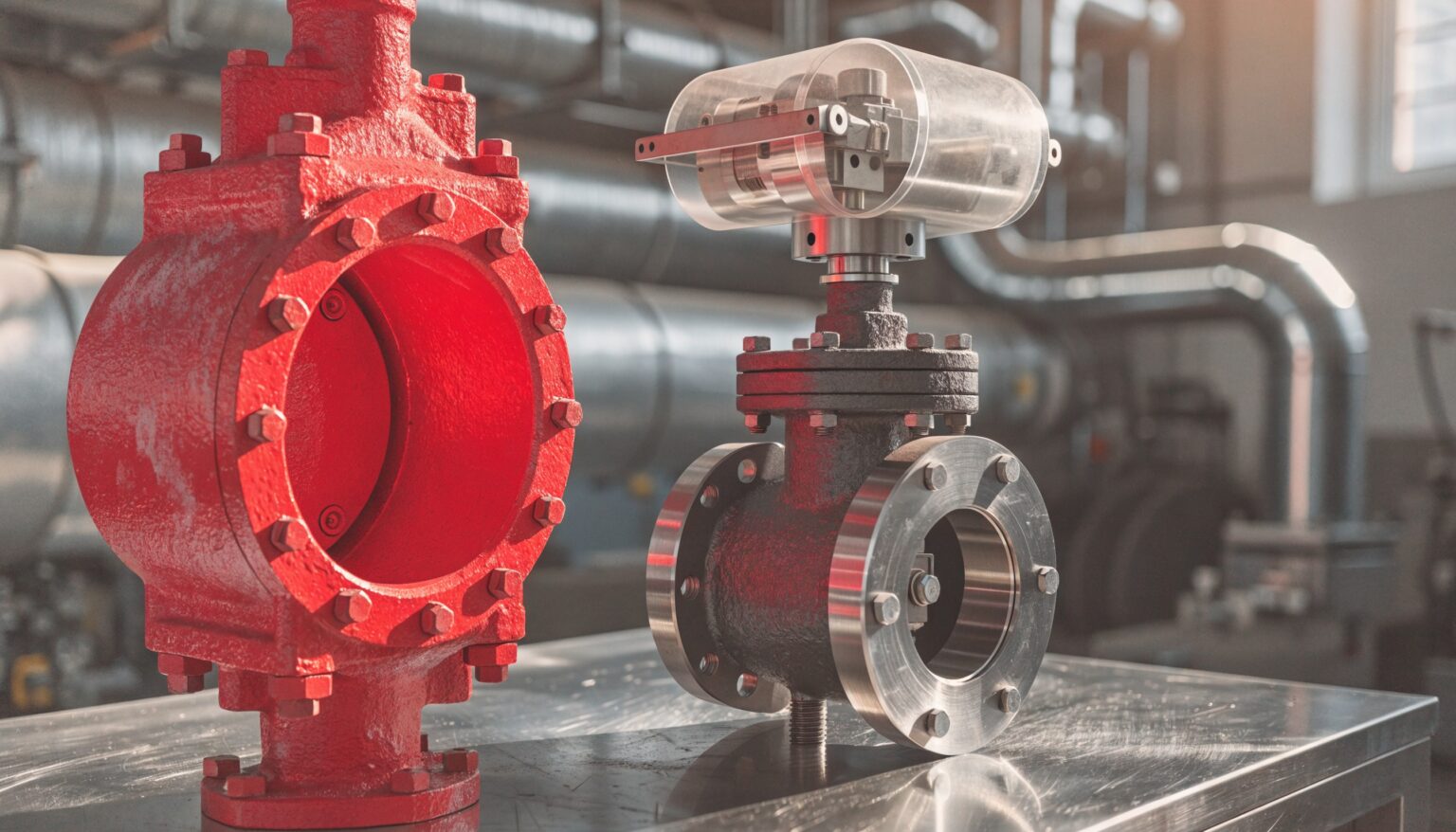
Regelklappe oder Regelventil – diese Frage steht in der Planung selten am Anfang, sie entscheidet aber über Stellgenauigkeit, Druckverlust, Baulänge, Antriebsgröße und damit über die Kosten einer ganzen Regelstrecke. Beide Bauarten regeln, beide gibt es über weite Nennweitenbereiche, und beide liegen bei uns im Programm. Der Unterschied liegt nicht in der Güte, sondern im Arbeitspunkt: Es gibt Regelaufgaben, bei denen ein Ventil einer Klappe klar überlegen ist, und es gibt Anwendungen, bei denen eine Klappe das Einzige ist, was in die Leitung passt. Dieser Beitrag ordnet die Kriterien so, dass Sie die Wahl an der Anlage treffen können und nicht erst im Datenblattvergleich.
Regelklappe oder Regelventil: der Unterschied liegt im Stellglied
Ein Regelventil arbeitet mit einem Kegel, der sich linear in einen Sitz bewegt. Das Medium wird umgelenkt, der Querschnitt verengt sich an einer konstruktiv festgelegten Stelle, und die Form des Kegels bestimmt, wie sich der Durchfluss über den Hub verändert – linear oder gleichprozentig. Die Kennlinie ist damit eine Entscheidung, die Sie mitbestellen.
Eine Regelklappe dreht eine Scheibe um eine Welle, üblicherweise über 90 Grad. Im offenen Zustand bleibt der Durchgang nahezu frei, die Scheibe steht nur als Widerstand in der Strömung. Die Kennlinie ergibt sich deshalb überwiegend aus der Geometrie und verläuft s-förmig: Im mittleren Stellbereich reagiert die Klappe stark, an beiden Rändern kaum.
Aus diesen zwei Absätzen folgt fast alles Weitere. Das Ventil ist das Werkzeug für genaue Dosierung gegen hohen Druckabfall. Die Klappe ist das Werkzeug für große Mengen bei geringem Druckverlust.
Kvs-Bereich und Baugröße sortieren die Kandidaten vor
Die schnellste Vorauswahl treffen Nennweite und Kvs-Wert. Unsere Regelventile decken DN 15 bis DN 600 bei PN 10 bis PN 630 ab, die Drossel- und Regelklappen DN 50 bis DN 3000 bei Mediumstemperaturen bis 1000 Grad Celsius.
Die Überschneidung liegt also zwischen DN 50 und DN 600 – und genau dort wird tatsächlich entschieden. Darunter gibt es faktisch keine Klappe, darüber kein wirtschaftliches Hubventil: Eine Armatur in DN 800 wird mit dem Kran eingebracht, und ihr Antrieb macht einen erheblichen Teil des Preises aus.
Innerhalb der Überschneidung hilft der Kvs-Wert weiter. Kleine Kvs-Werte, wie sie bei Einspritzwasser-, Abschlamm- und Absalzleitungen vorkommen, sind Ventilterrain. Eine Klappe in der passenden Nennweite hätte dort einen viel zu großen Kvs und stünde dauerhaft im unteren, unbrauchbaren Teil ihres Stellbereichs. Große Kvs-Werte bei kleiner Druckdifferenz sind umgekehrt der klassische Klappenfall.
Druckverhältnis, Kavitation und Schallpegel
Der zweite harte Filter ist das Druckverhältnis, also die Druckdifferenz über der Armatur im Verhältnis zum Vordruck.
Ein Regelventil kann die Drosselung auf mehrere Stufen verteilen – über die Kegelform, über Lochkäfige oder über mehrstufige Drosselelemente. Der Druck wird dann nicht an einer Kante abgebaut, sondern in Schritten. Bei Flüssigkeiten hält das den statischen Druck über dem Dampfdruck und verhindert, dass Dampfblasen entstehen und implodieren. Bei Gasen und Dampf begrenzt es den Schallpegel.
Eine Klappe drosselt an einer einzigen Stelle: am Spalt zwischen Scheibenrand und Gehäuse. Bei hohem Druckverhältnis entsteht dort die höchste Strömungsgeschwindigkeit der ganzen Strecke. In Flüssigkeit führt das zu Kavitation, und Kavitation frisst zuerst den Scheibenrand und dann das Gehäuse. In Gas führt es zu Schallpegeln, die bei der Abnahme zum Thema werden.
Als Arbeitsregel: Wird über der Armatur mehr als etwa die Hälfte des Vordrucks abgebaut und ist das Medium flüssig, gehört die Aufgabe zum Ventil. Bei Gas und Dampf verschiebt sich die Grenze, die Richtung bleibt dieselbe.
Das Medium entscheidet mit
Abgas, Rauchgas, Luft und andere große Volumenströme sind Klappenanwendungen, und zwar weitgehend unabhängig vom Druckverhältnis – schlicht, weil der Volumenstrom kein Ventil in vernünftiger Größe zulässt. Für diesen Bereich gibt es Klappen auch mit rechteckigem Gehäuse und in Ausführungen nach den lufttechnischen Normen DIN 24152 und DIN 24154. Das ist eine Information zur Ausführung, kein Auswahlargument für sich.
Medien mit Feststoffanteilen sprechen ebenfalls für die Klappe. Ein Kegel-Sitz-Paar ist eine enge Dichtstelle, die sich zusetzt oder ausgewaschen wird; der freie Durchgang der offenen Klappe ist dagegen unempfindlich.
Speisewasser, Einspritzwasser und Dampf mit hohem Druckabfall sind umgekehrt Ventilanwendungen. Hier zählt die genaue Dosierung kleiner Mengen gegen große Druckdifferenzen, und dafür gibt es die besonderen Bauformen: Speisewasser-Regelventile mit integriertem Pumpenfreilauf, Einspritzwasser-Regelventile, Abschlamm- und Absalzventile.
Beim Werkstoff nehmen sich die beiden Bauarten wenig. Für beide stehen unter anderem EN-GJL-250, P250GH, GP240GH+N, 13CrMo44, G17CrMo5-5 und Edelstähle zur Verfügung. Die Werkstoffwahl folgt der Temperatur und dem Medium, nicht der Bauart – sie ist deshalb selten das Kriterium, das die Entscheidung zwischen Klappe und Ventil kippt.
Baulänge, Gewicht und die Einbausituation
In der Sanierung ist die Einbaulänge oft das erste und das letzte Kriterium. Klappen gibt es als Zwischenflansch-Ausführung (wafer), als Anflansch-Ausführung (lug), als Doppelflansch-Klappe sowie mit Anschweißenden. Die Zwischenflanschklappe ist davon die kürzeste und leichteste Bauform und passt häufig dort, wo sonst nichts mehr hineingeht.
Ein Regelventil vergleichbarer Nennweite braucht deutlich mehr Baulänge und bringt ein Vielfaches an Masse mit. In einer bestehenden Leitung heißt das: nicht nur die Flanschanschlüsse prüfen, sondern auch die Rohrunterstützung und die zulässigen Kräfte am Stutzen. Wer eine alte Armatur eins zu eins ersetzen will, scheitert erfahrungsgemäß seltener an der Hydraulik als an diesen beiden Zentimetern.
Umgekehrt gilt: Wenn die Strecke ohnehin neu gezogen wird, ist die Baulänge kein Argument mehr und die Entscheidung fällt allein über Regelverhalten und Medium.
Stellgenauigkeit im unteren Hubbereich
Der nutzbare Regelbereich – das Verhältnis zwischen größtem und kleinstem sicher regelbarem Durchfluss – trennt die beiden Bauarten deutlicher als jede andere Kennzahl.
Eine Regelklappe arbeitet brauchbar zwischen etwa 20 und 70 Grad Öffnungswinkel. Unterhalb von 20 Grad steht die Scheibe fast im Sitz: Kleine Winkeländerungen ergeben große Durchflussänderungen, die Regelung wird unruhig, und der Spalt ist zugleich die Stelle mit der höchsten Erosionsbelastung. Oberhalb von 70 Grad passiert das Gegenteil – der Antrieb fährt, der Durchfluss bleibt praktisch unverändert.
Ein Regelventil regelt über den gesamten Hub und lässt sich über die Kegelform auf die Strecke abstimmen. Wenn Ihre Anlage zwischen Teillast und Volllast einen weiten Bereich abdecken muss, ist das der Punkt, an dem das Ventil gewinnt. Für besonders weite Bereiche gibt es Kaskaden-Regelventile, die zwei Stellstufen in einer Armatur zusammenfassen.
Ist die Klappe aus anderen Gründen gesetzt, lässt sich der Nachteil entschärfen: eine Nennweite kleiner als die Leitung wählen, damit der Arbeitspunkt in den mittleren Winkelbereich rückt. Das kostet etwas Druckverlust bei Volllast und bringt dafür ein ruhiges Regelverhalten im Teillastbetrieb.
Antrieb, Stellmoment und das Verhalten im Störfall
Die Klappe braucht einen Schwenkantrieb, das Ventil einen Hubantrieb. Das Stellmoment einer Klappe steigt mit der Nennweite und mit der Druckdifferenz, und es steigt schneller, als viele Auslegungen erwarten: Eine Klappe, die hydraulisch passt, kann am Antrieb scheitern. Der Anbau erfolgt üblicherweise nach ISO 5211, was die spätere Nachrüstung oder den Tausch des Antriebs erleichtert. Beide Bauarten gibt es mit Handbetätigung oder mit elektrischem, pneumatischem oder hydraulischem Antrieb.
Entscheidend wird der Antrieb dort, wo die Armatur im Störfall eine definierte Stellung einnehmen muss. Für Motor-Regelventile stehen dafür Lösungen mit hydraulischem Schnellschluss, mit Akku-Pack oder mit Notstromversorgung zur Verfügung. Wer diese Anforderung hat, sollte sie früh nennen – sie verschiebt die Auswahl oft stärker als die Hydraulik der Regelstrecke. Die Inbetriebnahme und die spätere Betreuung der Antriebe vor Ort übernimmt unsere eigene Serviceabteilung.
Fünf Fragen, die die Entscheidung abkürzen
- Welche Nennweite? Unter DN 50 bleibt nur das Ventil, ab DN 600 praktisch nur die Klappe. Dazwischen entscheiden die folgenden vier Fragen.
- Wie groß ist die Druckdifferenz im Verhältnis zum Vordruck? Über etwa der Hälfte und mit flüssigem Medium: Ventil, wegen der Kavitation.
- Was strömt? Abgas, Luft, große Volumenströme oder Medien mit Feststoffanteilen: Klappe. Speisewasser, Einspritzwasser, Dampf mit hohem Druckabfall: Ventil.
- Wie weit muss der Regelbereich reichen? Weiter Bereich mit sauberem Teillastverhalten: Ventil oder Kaskadenlösung.
- Was gibt die Einbausituation her? Enge Baulänge, begrenzte Tragfähigkeit oder ein Tausch im Bestand: Zwischenflanschklappe prüfen.
Häufige Fragen zur Auswahl zwischen Regelklappe und Regelventil
Kann eine Absperrklappe auch regeln?
Kurzzeitig ja, dauerhaft nein. Eine Absperrklappe ist für die Endlagen konstruiert und dort auf Dichtheit optimiert. In Zwischenstellungen liegt die Scheibe dauerhaft in der Strömung, die Sitzdichtung wird angeströmt und verschleißt genau dort, wo sie später dicht sein soll. Für Regelaufgaben ist die Drossel- oder Regelklappe die richtige Bauform; ihr Scheibenprofil und ihre Lagerung sind für den Dauerbetrieb in Zwischenstellungen ausgelegt.
Was ist der häufigste Fehler bei der Auslegung?
Die Armatur wird auf die Nennweite der Leitung ausgelegt statt auf den tatsächlichen Durchfluss. Das Ergebnis ist ein zu großer Kvs-Wert: Das Stellglied arbeitet im Betrieb nur im untersten Bereich seines Hubs oder Winkels, die Regelung pendelt, und der Verschleiß konzentriert sich auf eine schmale Zone. Dieser Fehler trifft Klappe und Ventil gleichermaßen, bei der Klappe wirkt er sich wegen des schmalen nutzbaren Winkelbereichs nur früher aus.
Ab welcher Nennweite ist die Klappe gesetzt?
Eine harte Grenze gibt es nicht, aber ab etwa DN 300 bis DN 400 kippt die Rechnung meist zugunsten der Klappe: Gewicht, Baulänge, Antriebsgröße und Preis des Hubventils steigen stärker als der Nutzen im Regelverhalten. Oberhalb von DN 600 endet unser Ventilprogramm, dort ist die Klappe ohnehin die Antwort.
Lässt sich ein vorhandenes Regelventil durch eine Klappe ersetzen?
Wenn Druckverhältnis und Regelbereich es zulassen, ja – und die Baulänge spricht dann meist für den Tausch. Zu prüfen sind drei Punkte: das Druckverhältnis im Auslegungspunkt, der geforderte Regelbereich im Teillastbetrieb und das Stellmoment des vorhandenen oder neuen Antriebs. Schicken Sie uns die Betriebsdaten der Strecke, dann rechnen wir beide Varianten gegeneinander.
Fazit
Die Frage Regelklappe oder Regelventil lässt sich fast immer mit zwei Zahlen und einem Medium beantworten: Nennweite, Druckverhältnis und das, was durch die Leitung geht. Große Mengen bei kleinem Druckabfall gehören der Klappe, genaue Dosierung gegen hohen Druckabfall dem Ventil, und der Bereich dazwischen wird über Regelbereich, Baulänge und Antrieb entschieden.
Wir führen beide Bauarten aus einer Hand, rechnen die Auslegung für Ihren Betriebspunkt und betreuen die Armatur danach vor Ort – in Österreich seit 1983 und in unserem Vertriebsgebiet in Südosteuropa. Schicken Sie uns Durchfluss, Vor- und Nachdruck, Medium, Temperatur und die Einbaulänge, dann bekommen Sie einen Vorschlag mit Kvs-Wert, Bauart und Antrieb.
Control butterfly valve or globe control valve: which final control element for which duty
Butterfly or globe – the question rarely comes first in the design phase, yet it governs control accuracy, pressure loss, face-to-face length, actuator size and therefore the cost of an entire control loop. Both designs control, both are available across wide nominal size ranges, and we supply both. The difference is not one of quality but of operating point: there are duties where a globe control valve is clearly superior to a butterfly valve, and there are installations where a butterfly valve is the only thing that will physically fit the line. This article sorts the criteria so that you can make the decision at the plant rather than in a datasheet comparison.
The difference lies in the closing element
A globe control valve works with a plug that travels linearly into a seat. The medium is deflected, the cross-section narrows at a defined point, and the shape of the plug determines how flow changes over the stroke – linear or equal percentage. The inherent characteristic is therefore something you specify when you order.
A control butterfly valve rotates a disc around a shaft, typically through 90 degrees. In the open position the bore stays almost clear and the disc acts only as a resistance in the flow. The characteristic therefore follows mainly from geometry and is S-shaped: the valve responds strongly in the middle of its travel and barely at either end.
Almost everything else follows from those two paragraphs. The globe valve is the tool for accurate metering against a high pressure drop. The butterfly valve is the tool for large quantities at low pressure loss.
Kvs range and nominal size narrow the field first
The fastest pre-selection comes from nominal size and Kvs value. Our control valves cover DN 15 to DN 600 at PN 10 to PN 630; the throttling and control butterfly valves cover DN 50 to DN 3000 at medium temperatures up to 1000 degrees Celsius.
The overlap therefore lies between DN 50 and DN 600, and that is exactly where the decision is actually made. Below it there is effectively no butterfly valve; above it there is no economical globe valve, because a DN 800 unit has to be lifted in by crane and its actuator accounts for a substantial share of the price.
Within the overlap the Kvs value settles it. Small Kvs values, as found on injection water, blowdown and continuous blowdown lines, are globe valve territory. A butterfly valve of matching nominal size would have a far too large Kvs and would sit permanently in the lower, unusable part of its travel. Large Kvs values at small differential pressure are the classic butterfly case.
Pressure ratio, cavitation and noise
The second hard filter is the pressure ratio, meaning the differential pressure across the valve relative to the inlet pressure.
A globe control valve can distribute the throttling over several stages – through the plug contour, through cages, or through multi-stage trim. Pressure is then reduced in steps rather than at a single edge. In liquids this keeps the static pressure above the vapour pressure and prevents vapour bubbles from forming and collapsing. In gas and steam it limits the sound pressure level.
A butterfly valve throttles at one place only: the gap between disc edge and body. At a high pressure ratio this is where the highest flow velocity in the whole line occurs. In liquid that causes cavitation, and cavitation attacks the disc edge first and the body second. In gas it produces noise levels that become an issue at acceptance.
As a working rule: if more than roughly half the inlet pressure is destroyed across the valve and the medium is a liquid, the duty belongs to a globe valve. With gas and steam the threshold shifts, but the direction stays the same.
The medium has a say
Flue gas, exhaust gas, air and other large volume flows are butterfly applications, largely regardless of the pressure ratio – simply because the volume flow leaves no globe valve of sensible size. For this field the butterfly valves are also available with rectangular bodies and in versions to the ventilation standards DIN 24152 and DIN 24154. That is information about the design, not a selection argument in itself.
Media carrying solids also favour the butterfly valve. A plug and seat form a narrow sealing point that clogs or washes out; the clear bore of an open butterfly valve is insensitive to this.
Feed water, injection water and steam with a high pressure drop are globe valve applications. Here what counts is accurate metering of small quantities against large differential pressures, and that is what the special designs are for: feed water control valves with integrated pump recirculation, injection water control valves, blowdown and continuous blowdown valves.
Materials barely separate the two designs. Both are available in EN-GJL-250, P250GH, GP240GH+N, 13CrMo44, G17CrMo5-5 and stainless steels, among others. Material selection follows temperature and medium rather than valve type, so it is rarely the criterion that decides between butterfly and globe.
Face-to-face length, weight and the installation
In a retrofit the installed length is often the first and the last criterion. Butterfly valves are available as wafer type, as lug type, as double flanged valves and with butt weld ends. The wafer type is the shortest and lightest of these and frequently fits where nothing else will.
A globe control valve of comparable nominal size needs considerably more face-to-face length and brings several times the mass. In an existing line that means checking not only the flange connections but also the pipe supports and the permissible nozzle loads. Anyone replacing an old valve one for one fails less often on the hydraulics than on those few centimetres.
Conversely, if the line is being newly routed anyway, face-to-face length stops being an argument and the decision rests on control behaviour and medium alone.
Control accuracy at the lower end of travel
The usable rangeability – the ratio between the largest and the smallest flow that can still be controlled reliably – separates the two designs more clearly than any other figure.
A control butterfly valve works well between roughly 20 and 70 degrees of opening angle. Below 20 degrees the disc sits almost in the seat: small changes in angle produce large changes in flow, control becomes unstable, and the gap is at the same time the point of highest erosion load. Above 70 degrees the opposite happens – the actuator travels and the flow stays practically unchanged.
A globe control valve controls over its entire stroke and can be matched to the loop through the plug contour. If your plant has to cover a wide range between part load and full load, that is where the globe valve wins. For particularly wide ranges there are cascade control valves, which combine two control stages in one body.
If a butterfly valve is set for other reasons, the drawback can be reduced: select one nominal size smaller than the line so that the operating point moves into the middle angular range. This costs some pressure loss at full load and returns stable control behaviour at part load.
Actuator, torque and behaviour in a fault condition
The butterfly valve needs a quarter-turn actuator, the globe valve a linear actuator. The torque required by a butterfly valve rises with nominal size and with differential pressure, and it rises faster than many calculations expect: a butterfly valve that fits hydraulically can still fail on the actuator. Mounting is usually to ISO 5211, which makes later retrofitting or replacement of the actuator easier. Both designs are available with hand operation or with electric, pneumatic or hydraulic actuators.
The actuator becomes decisive wherever the valve has to assume a defined position in a fault condition. For motor-operated control valves there are solutions with hydraulic quick-closing, with a battery pack or with an emergency power supply. If you have that requirement, state it early – it shifts the selection more often than the hydraulics of the loop do. Commissioning and later on-site support of the actuators are handled by our own service department.
Five questions that shorten the decision
- Which nominal size? Below DN 50 only the globe valve remains; from DN 600 upwards, practically only the butterfly valve. In between, the following four questions decide.
- How large is the differential pressure relative to the inlet pressure? Above roughly half, with a liquid medium: globe valve, because of cavitation.
- What is flowing? Exhaust gas, air, large volume flows or media carrying solids: butterfly valve. Feed water, injection water, steam with a high pressure drop: globe valve.
- How wide does the control range have to be? Wide range with clean part-load behaviour: globe valve or a cascade solution.
- What does the installation allow? Tight face-to-face length, limited support capacity or a replacement in an existing line: check the wafer type butterfly valve.
Frequently asked questions
Can an isolation butterfly valve also control?
For short periods yes, permanently no. An isolation butterfly valve is built for its end positions and optimised for tightness there. In intermediate positions the disc stays in the flow, the seat liner is exposed to it and wears exactly where it is later meant to seal. For control duties the throttling or control butterfly valve is the correct design; its disc profile and bearings are laid out for continuous operation in intermediate positions.
What is the most common sizing mistake?
The valve is sized to the nominal size of the line instead of to the actual flow. The result is an oversized Kvs value: in operation the closing element works only in the lowest part of its stroke or angle, control hunts, and wear concentrates in a narrow zone. This mistake affects butterfly and globe valves alike; on a butterfly valve it simply shows up earlier because the usable angular range is narrower.
From which nominal size is the butterfly valve set?
There is no hard limit, but from roughly DN 300 to DN 400 the calculation usually tips towards the butterfly valve: weight, face-to-face length, actuator size and price of the globe valve rise faster than the benefit in control behaviour. Above DN 600 our globe valve range ends, and there the butterfly valve is the answer in any case.
Can an existing globe control valve be replaced by a butterfly valve?
If the pressure ratio and the required rangeability allow it, yes – and the face-to-face length then usually argues in favour of the swap. Three points need checking: the pressure ratio at the design point, the rangeability required at part load, and the torque of the existing or new actuator. Send us the operating data of the loop and we will calculate both options against each other.
Conclusion
Butterfly or globe can almost always be answered with two figures and a medium: nominal size, pressure ratio and whatever runs through the line. Large quantities at a small pressure drop belong to the butterfly valve, accurate metering against a high pressure drop to the globe valve, and the field in between is decided by rangeability, face-to-face length and actuator.
We supply both designs from one source, calculate the sizing for your operating point and support the valve on site afterwards – in Austria since 1983 and across our sales territory in South-Eastern Europe. Send us flow rate, inlet and outlet pressure, medium, temperature and installed length, and you will receive a proposal with Kvs value, valve type and actuator.
