
Druckverlust von Absperrarmaturen: Absperrklappe, Schieber oder Ventil — wann der Zeta-Wert die Wahl entscheidet
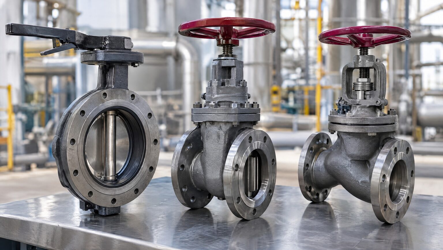
Der Druckverlust einer Absperrklappe, eines Absperrschiebers oder eines Absperrventils wird bei der Armaturenwahl oft gar nicht gerechnet – die Armatur ist im Betrieb ja offen. Genau dort kostet sie aber Druck, und zwar in jeder Betriebsstunde. Bei einer kurzen Nebenleitung spielt das keine Rolle. Bei einer Kühlwasser-Hauptleitung im Dauerbetrieb, auf der Saugseite einer Pumpe oder in einer Niederdruck-Dampfleitung kann es die Wahl entscheiden. Dieser Beitrag zeigt, wie Sie den Druckverlust offener Absperrarmaturen über den Zeta-Wert abschätzen, wie Zeta- und Kv-Wert zusammenhängen, wo Klappe, Schieber und Ventil typischerweise liegen und in welchen Fällen der Druckverlust das ausschlaggebende Kriterium ist – und wann nicht.
Druckverlust Absperrklappe, Schieber, Ventil: die Formel dahinter
Für jede durchströmte Armatur gilt dieselbe Beziehung: Δp = ζ · ρ · v² / 2. Der Druckverlust ist das Produkt aus dem Widerstandsbeiwert ζ (Zeta) der Armatur und dem Staudruck der Strömung, also Dichte mal Geschwindigkeit im Quadrat, halbiert. Zwei Dinge folgen daraus unmittelbar. Erstens geht die Geschwindigkeit quadratisch ein: Doppelter Volumenstrom bei gleicher Nennweite bedeutet vierfachen Druckverlust. Zweitens ist ζ eine Eigenschaft der Bauart und der konkreten Armatur, nicht des Mediums. Derselbe Schieber hat in Wasser und in Dampf denselben Beiwert, wegen der völlig unterschiedlichen Dichte und Geschwindigkeit aber einen ganz anderen Druckverlust.
Der ζ-Wert bezieht sich auf die Strömungsgeschwindigkeit im Anschlussquerschnitt, also in der Nennweite der Armatur. Hat eine Armatur einen reduzierten Durchgang, steckt das bereits im ζ-Wert – er ist dann deutlich größer als bei der Ausführung mit vollem Durchgang. Beim Vergleich zweier Datenblätter lohnt deshalb immer der Blick, ob beide Armaturen vollen Durchgang haben.
Zeta-Wert und Kv-Wert: zwei Angaben für dieselbe Sache
Hersteller geben den Durchflusswiderstand entweder als ζ-Wert oder als Kv-Wert an. Der Kv-Wert ist der Volumenstrom Wasser in m³/h, der bei 1 bar Druckverlust durch die voll geöffnete Armatur geht. Für Flüssigkeiten folgt daraus direkt: Δp [bar] = (Q / Kv)² · ρ / 1000, mit Q in m³/h und ρ in kg/m³. Wer den Kv-Wert aus dem Datenblatt hat, braucht ζ also gar nicht.
Umgekehrt lassen sich beide Angaben ineinander umrechnen: ζ = 0,0016 · d⁴ / Kv², mit d als Innendurchmesser in Millimetern und Kv in m³/h. Für DN 200 heißt das zum Beispiel: Ein ζ von 0,2 entspricht einem Kv von rund 3.600 m³/h, ein ζ von 4 einem Kv von rund 800 m³/h. Die Umrechnung ist nützlich, wenn zwei Datenblätter verschiedene Angaben machen – etwa der eine Hersteller den Kv-Wert, der andere den ζ-Wert. Die Auslegung von Regelventilen über Kvs-Wert und Ventilautorität ist ein eigenes Thema, dazu mehr im Beitrag Regelventil auslegen. Bei Absperrarmaturen geht es nur um den Widerstand in Offenstellung.
Typische ζ-Werte: Schieber, Kugelhahn, Klappe, Ventil
So ist verglichen: Verglichen werden Bauarten, nicht Anbieter oder Fabrikate. Die Werte sind Richtwerte für die voll geöffnete Armatur aus der gängigen Fachliteratur zur Rohrleitungshydraulik und aus Herstellerangaben, Stand November 2026. Sie zeigen Größenordnungen. Für die Berechnung einer Anlage gilt immer der ζ- oder Kv-Wert aus dem Datenblatt der konkreten Armatur.
- Absperrschieber mit vollem Durchgang: ζ etwa 0,1 bis 0,3. In Offenstellung ist der Keil ganz aus dem Strömungsweg gezogen, das Medium sieht fast nur ein Rohrstück.
- Kugelhahn mit vollem Durchgang: ζ etwa 0,1 und darunter. Mit reduziertem Durchgang steigt der Wert deutlich.
- Absperrklappe: ζ etwa 0,2 bis 1,5. Die Scheibe bleibt auch offen im Strom. Bei großen Nennweiten ist ihr Anteil am Querschnitt klein und der Wert liegt unten im Bereich, bei kleinen Nennweiten und dicken Scheiben von Hochdruckklappen eher oben.
- Absperrventil in Schrägsitzform: ζ etwa 1 bis 3.
- Absperrventil in Geradsitzform: ζ etwa 3 bis 6, je nach Bauform auch darüber. Das Medium wird zweimal umgelenkt und durch den Sitz geführt.
Zwischen Schieber und Geradsitzventil liegt damit rund ein Faktor 20. Zwischen Schieber und Klappe ist der Unterschied bei großen Nennweiten oft gering – deshalb sind Klappen dort häufig die wirtschaftlichere Wahl, ohne dass beim Druckverlust viel verloren geht.
Rechenbeispiel: DN 200 Kühlwasser im Dauerbetrieb
Angenommen sind Wasser, DN 200 und eine Strömungsgeschwindigkeit von 2 m/s, das sind rund 226 m³/h. Der Staudruck beträgt ρ · v² / 2 = 1.000 · 4 / 2 = 2.000 Pa, also 0,02 bar. Mit den Richtwerten von oben ergibt sich:
- Schieber, ζ = 0,2: 400 Pa, rund 0,004 bar
- Klappe, ζ = 0,5: 1.000 Pa, 0,01 bar
- Geradsitzventil, ζ = 4: 8.000 Pa, 0,08 bar
Für sich genommen sind das kleine Zahlen. Interessant wird es in Pumpenleistung: Hydraulische Leistung ist Volumenstrom mal Druckverlust. Bei 0,063 m³/s sind das für das Ventil rund 500 W, für die Klappe rund 63 W, für den Schieber rund 25 W. Mit einem angenommenen Pumpenwirkungsgrad von 70 % braucht die Pumpe für das Geradsitzventil rund 0,7 kW mehr Antriebsleistung, über 8.000 Betriebsstunden im Jahr sind das rund 5.700 kWh. Für den Schieber sind es im selben Fall rund 290 kWh, für die Klappe rund 720 kWh. Das ist die Größenordnung, über die bei einer Dauerbetriebsleitung entschieden wird – je Armatur, und in einer Leitung sitzen meist mehrere.
Eine zweite Lesart hilft beim Gefühl für die Größenordnung: die gleichwertige Rohrlänge. Ein neues Stahlrohr DN 200 hat bei dieser Strömung eine Rohrreibungszahl um 0,015, also einen Widerstand von etwa ζ = 0,075 je Meter. Der Schieber wirkt damit wie knapp drei Meter zusätzliches Rohr, die Klappe wie rund sieben Meter, das Geradsitzventil wie gut 50 Meter.
Wann der Druckverlust die Wahl entscheidet
- Große Volumenströme im Dauerbetrieb: Kühlwasser, Fernwärme, Speisewasser, Umwälzkreise. Hier summiert sich der Druckverlust in jeder Betriebsstunde, siehe Rechenbeispiel.
- Saugseite von Pumpen: Jeder Druckverlust vor der Pumpe senkt den verfügbaren Zulaufdruck, also den NPSH-Wert der Anlage. Bei knapper Reserve kann ein Ventil statt eines Schiebers in der Saugleitung den Unterschied zwischen ruhigem Lauf und Kavitation ausmachen. Saugseitig gehört deshalb eine Armatur mit kleinem ζ hin.
- Anlagen mit wenig verfügbarem Druck: Schwerkraftleitungen, Kondensatrückführung ohne Pumpe, Niederdruckdampf. Wo insgesamt nur wenige Zehntel bar zur Verfügung stehen, ist ein Zehntel bar an einer einzelnen Armatur viel.
- Lange Leitungen mit vielen Armaturen: Fünf Geradsitzventile hintereinander wirken in der Druckverlustrechnung wie mehr als 250 Meter zusätzliches Rohr.
Wann andere Kriterien wichtiger sind
In vielen Fällen ist der Druckverlust zwar da, aber nicht entscheidend. Das Absperrventil wird nicht wegen seines Strömungswiderstands gewählt, sondern trotz ihm: Es schließt über einen kurzen Hub, der Sitz lässt sich bei hohen Drücken und Temperaturen zuverlässig dicht bekommen, es verträgt häufiges Schalten, und mit Faltenbalg-Spindelabdichtung ist die Spindel nach außen ohne Stopfbuchse abgedichtet. Bei kleinen Nennweiten, kurzen Betriebszeiten oder in Leitungen, in denen ohnehin ein Regelventil den größten Teil des Drucks abbaut, fällt der höhere ζ-Wert kaum ins Gewicht.
Auch die Klappe wird selten wegen ζ gewählt, sondern wegen Baulänge, Gewicht und Preis bei großen Nennweiten, der Schieber wegen seines geraden Durchgangs und bei Dampf und hohen Drücken wegen seiner Bauform. Wichtig für alle drei: Absperrarmaturen sind für die Stellungen Auf und Zu gedacht. Wer einen Schieber oder eine Absperrklappe zum Drosseln teilweise öffnet, verlässt den Bereich, für den der ζ-Wert gilt. Bei kleinen Öffnungswinkeln steigt der Widerstand einer Klappe steil an, an Sitz und Scheibe entstehen hohe Geschwindigkeiten. Dafür gibt es Regelventile und Drossel- und Regelklappen.
Dampf: kleiner Staudruck, andere Wirkung
In Dampfleitungen ist die Dichte klein und die Geschwindigkeit groß. Sattdampf mit 10 bar absolut hat eine Dichte von rund 5,2 kg/m³, bei 30 m/s liegt der Staudruck bei rund 2.300 Pa – also in derselben Größenordnung wie im Wasserbeispiel. Ein Geradsitzventil mit ζ = 4 kostet dann knapp 0,1 bar, eine Klappe mit ζ = 0,5 gut 0,01 bar. Bei Hochdruckdampf fällt das kaum ins Gewicht. Bei Niederdruckdampf, wo der Druck an der Verbrauchsstelle ohnehin knapp ist, kann es die Leistung eines Wärmetauschers spürbar senken, weil mit dem Druck auch die Sattdampftemperatur sinkt. Beim Anfahren zählt bei Dampf außerdem nicht die Offenstellung, sondern wie die Armatur geöffnet und die Leitung vorgewärmt wird – dazu mehr im Beitrag zum Dampfschieber.
Was in die Anfrage gehört
Damit der Druckverlust bei der Auswahl berücksichtigt werden kann, braucht es in der Anfrage mehr als Nennweite und Druckstufe: Medium, Betriebsdruck und -temperatur, Volumenstrom im Normalbetrieb, die Betriebsart – dauernd durchströmt oder nur gelegentlich – und, wo es eng wird, den zulässigen Druckverlust je Armatur oder die NPSH-Reserve auf der Saugseite. Dann lässt sich für jede Bauart der ζ- oder Kv-Wert aus dem Datenblatt des Herstellers einsetzen statt eines Richtwerts.
Ing. Wilhelm Friedrich Gesellschaft m. b. H. führt alle drei Bauarten: Absperrklappen von DN 65 bis DN 2500 in Zwischenflansch-, Anflansch- und Doppelflanschausführung, Absperrschieber von DN 50 bis DN 1000 bis PN630, auch mit Bypass, und Absperrventile von DN 10 bis DN 200 bis PN630, auf Wunsch mit Faltenbalg-Spindelabdichtung. Wo ein besonders kleiner Durchflusswiderstand gefragt ist, kommen Kugelhähne dazu.
Häufige Fragen zum Druckverlust von Absperrarmaturen
Wo finde ich den ζ-Wert einer Armatur?
Im Datenblatt des Herstellers, als ζ- oder Kv-Wert für die voll geöffnete Armatur. Fehlt die Angabe, fragen Sie sie beim Lieferanten an. Richtwerte aus Tabellen ersetzen sie für die Auslegung nicht.
Hat eine Absperrklappe mehr Druckverlust als ein Schieber?
In der Regel ja, weil die Scheibe auch in Offenstellung im Strom steht. Bei großen Nennweiten ist der Unterschied klein, bei kleinen Nennweiten und dicken Scheiben deutlicher. Ob er zählt, zeigt erst die Rechnung mit Volumenstrom und Betriebsstunden.
Kann ich den Druckverlust mit einer größeren Nennweite ausgleichen?
Ja. Weil die Geschwindigkeit quadratisch eingeht, senkt schon eine Nennweitenstufe mehr den Druckverlust deutlich. Ob sich das rechnet, hängt vom Preis der größeren Armatur und der Reduzierstücke ab – und die verursachen selbst wieder Druckverlust.
Gilt der ζ-Wert auch für die teilweise geöffnete Armatur?
Nein. Er gilt für die voll geöffnete Armatur. Für Zwischenstellungen geben Hersteller von Regelarmaturen Kennlinien an. Absperrarmaturen sind für den Drosselbetrieb nicht ausgelegt.
Fazit: Druckverlust rechnen, wo er Betriebsstunden kostet
Der Druckverlust einer offenen Absperrarmatur folgt aus ζ-Wert und Staudruck. Schieber und Kugelhahn mit vollem Durchgang liegen am unteren Ende, die Absperrklappe meist knapp darüber, das Geradsitzventil um ein Vielfaches höher. Entscheidend wird das bei großen Volumenströmen im Dauerbetrieb, auf der Saugseite von Pumpen und überall, wo wenig Druck zur Verfügung steht. In allen anderen Fällen wählen Sie die Armatur nach Dichtheit, Schaltverhalten, Baulänge und Druckstufe – und rechnen den Druckverlust trotzdem mit, mit den Werten aus dem Datenblatt. Ing. Wilhelm Friedrich Gesellschaft m. b. H. unterstützt Sie bei der Auswahl und mit der eigenen Serviceabteilung auch vor Ort.
Pressure loss of isolating valves: butterfly valve, gate valve or globe valve – when the zeta value decides
The pressure loss of a butterfly valve, a gate valve or a globe valve is often not calculated at all when the valve is selected – after all, the valve is open in operation. But that is exactly where it costs pressure, in every operating hour. On a short branch line this does not matter. On a cooling water main in continuous operation, on the suction side of a pump or in a low-pressure steam line it can decide the choice. This article shows how to estimate the pressure loss of open isolating valves from the zeta value, how zeta and Kv value are related, where butterfly, gate and globe valves typically lie, and in which cases pressure loss is the deciding criterion – and when it is not.
The formula behind it
The same relationship applies to every valve with flow through it: Δp = ζ · ρ · v² / 2. The pressure loss is the product of the resistance coefficient ζ (zeta) of the valve and the dynamic pressure of the flow, i.e. density times velocity squared, halved. Two things follow directly. First, velocity enters squared: twice the flow rate at the same nominal size means four times the pressure loss. Second, ζ is a property of the design and the specific valve, not of the medium. The same gate valve has the same coefficient in water and in steam, but because density and velocity are completely different, its pressure loss is entirely different.
The ζ value refers to the flow velocity in the connection cross-section, i.e. in the nominal size of the valve. If a valve has a reduced bore, this is already contained in the ζ value – it is then considerably higher than for the full-bore version. When comparing two data sheets, it is therefore always worth checking whether both valves are full bore.
Zeta value and Kv value: two figures for the same thing
Manufacturers state flow resistance either as a ζ value or as a Kv value. The Kv value is the flow rate of water in m³/h that passes through the fully open valve at a pressure loss of 1 bar. For liquids it follows directly: Δp [bar] = (Q / Kv)² · ρ / 1000, with Q in m³/h and ρ in kg/m³. If you have the Kv value from the data sheet, you do not need ζ at all.
Conversely, the two figures can be converted into each other: ζ = 0.0016 · d⁴ / Kv², with d as the internal diameter in millimetres and Kv in m³/h. For DN 200, for example: a ζ of 0.2 corresponds to a Kv of around 3,600 m³/h, a ζ of 4 to a Kv of around 800 m³/h. The conversion is useful when two data sheets give different figures – one manufacturer the Kv value, the other the ζ value. Sizing control valves via Kvs value and valve authority is a separate topic. For isolating valves, only the resistance in the open position matters.
Typical ζ values: gate valve, ball valve, butterfly valve, globe valve
How the comparison was made: Designs are compared, not suppliers or makes. The values are guide values for the fully open valve from common technical literature on piping hydraulics and from manufacturer data, as of November 2026. They show orders of magnitude. For calculating a plant, the ζ or Kv value from the data sheet of the specific valve always applies.
- Full-bore gate valve: ζ approx. 0.1 to 0.3. In the open position the wedge is pulled completely out of the flow path; the medium sees little more than a piece of pipe.
- Full-bore ball valve: ζ approx. 0.1 and below. With a reduced bore the value rises considerably.
- Butterfly valve: ζ approx. 0.2 to 1.5. The disc remains in the flow even when open. In large nominal sizes its share of the cross-section is small and the value is at the lower end; in small sizes and with the thick discs of high-pressure butterfly valves it tends towards the upper end.
- Y-pattern globe valve: ζ approx. 1 to 3.
- Straight-pattern globe valve: ζ approx. 3 to 6, depending on design also higher. The medium is deflected twice and guided through the seat.
Between gate valve and straight-pattern globe valve there is roughly a factor of 20. Between gate valve and butterfly valve the difference in large nominal sizes is often small – which is why butterfly valves are frequently the more economical choice there without losing much on pressure loss.
Worked example: DN 200 cooling water in continuous operation
Assume water, DN 200 and a flow velocity of 2 m/s, which is around 226 m³/h. The dynamic pressure is ρ · v² / 2 = 1,000 · 4 / 2 = 2,000 Pa, i.e. 0.02 bar. With the guide values above:
- Gate valve, ζ = 0.2: 400 Pa, around 0.004 bar
- Butterfly valve, ζ = 0.5: 1,000 Pa, 0.01 bar
- Straight-pattern globe valve, ζ = 4: 8,000 Pa, 0.08 bar
On their own these are small numbers. They become interesting in terms of pump power: hydraulic power is flow rate times pressure loss. At 0.063 m³/s this is around 500 W for the globe valve, around 63 W for the butterfly valve and around 25 W for the gate valve. With an assumed pump efficiency of 70 %, the pump needs around 0.7 kW more drive power for the globe valve; over 8,000 operating hours a year that is around 5,700 kWh. For the gate valve it is around 290 kWh in the same case, for the butterfly valve around 720 kWh. That is the order of magnitude decided on for a continuously operated line – per valve, and a line usually contains several.
A second way of reading it helps with the sense of scale: the equivalent pipe length. A new DN 200 steel pipe has a friction factor of around 0.015 at this flow, i.e. a resistance of about ζ = 0.075 per metre. The gate valve therefore acts like just under three metres of additional pipe, the butterfly valve like around seven metres, the straight-pattern globe valve like a good 50 metres.
When pressure loss decides the choice
- Large flow rates in continuous operation: cooling water, district heating, feedwater, circulation loops. Here the pressure loss adds up in every operating hour, see the worked example.
- Suction side of pumps: every pressure loss upstream of the pump reduces the available inlet pressure, i.e. the NPSH available of the plant. With a tight margin, a globe valve instead of a gate valve in the suction line can make the difference between smooth running and cavitation. On the suction side, a valve with a low ζ belongs there.
- Systems with little available pressure: gravity lines, condensate return without a pump, low-pressure steam. Where only a few tenths of a bar are available in total, a tenth of a bar at a single valve is a lot.
- Long lines with many valves: five straight-pattern globe valves in series act like more than 250 metres of additional pipe in the pressure loss calculation.
When other criteria matter more
In many cases the pressure loss exists but is not decisive. The globe valve is not chosen because of its flow resistance but despite it: it closes over a short stroke, its seat can be made reliably tight at high pressures and temperatures, it tolerates frequent operation, and with a bellows stem seal the stem is sealed to the outside without a gland packing. In small nominal sizes, with short operating times, or in lines where a control valve takes up most of the pressure anyway, its higher ζ value hardly matters.
The butterfly valve, too, is rarely chosen for its ζ, but for face-to-face length, weight and price in large nominal sizes; the gate valve for its straight-through bore and, in steam and at high pressures, for its design. Important for all three: isolating valves are intended for the open and closed positions. Anyone who partly opens a gate valve or a butterfly valve to throttle leaves the range for which the ζ value applies. At small opening angles the resistance of a butterfly valve rises steeply, and high velocities occur at seat and disc. Control valves and throttling and control butterfly valves exist for this purpose.
Steam: small dynamic pressure, different effect
In steam lines the density is low and the velocity high. Saturated steam at 10 bar absolute has a density of around 5.2 kg/m³; at 30 m/s the dynamic pressure is around 2,300 Pa – in the same order of magnitude as in the water example. A straight-pattern globe valve with ζ = 4 then costs just under 0.1 bar, a butterfly valve with ζ = 0.5 a little over 0.01 bar. With high-pressure steam this hardly matters. With low-pressure steam, where the pressure at the consumer is tight anyway, it can noticeably reduce the output of a heat exchanger, because the saturation temperature falls with the pressure. During start-up, what counts with steam is not the open position but how the valve is opened and the line is warmed up.
What belongs in the enquiry
For the pressure loss to be taken into account in the selection, the enquiry needs more than nominal size and pressure rating: medium, operating pressure and temperature, flow rate in normal operation, the mode of operation – continuous flow or only occasional – and, where it gets tight, the permissible pressure loss per valve or the NPSH margin on the suction side. Then the ζ or Kv value from the manufacturer’s data sheet can be used for each design instead of a guide value.
Ing. Wilhelm Friedrich Gesellschaft m. b. H. supplies all three designs: butterfly valves from DN 65 to DN 2500 in wafer, lug and double-flanged versions, gate valves from DN 50 to DN 1000 up to PN630, also with bypass, and globe valves from DN 10 to DN 200 up to PN630, with bellows stem seal on request. Where particularly low flow resistance is required, ball valves complete the range.
Frequently asked questions about the pressure loss of isolating valves
Where do I find the ζ value of a valve?
In the manufacturer’s data sheet, as a ζ or Kv value for the fully open valve. If it is missing, ask the supplier for it. Guide values from tables do not replace it for sizing.
Does a butterfly valve have more pressure loss than a gate valve?
As a rule, yes, because the disc stays in the flow even in the open position. In large nominal sizes the difference is small, in small sizes and with thick discs it is more pronounced. Whether it counts is only shown by the calculation with flow rate and operating hours.
Can I compensate for pressure loss with a larger nominal size?
Yes. Because velocity enters squared, even one nominal size step up reduces the pressure loss considerably. Whether it pays off depends on the price of the larger valve and the reducers – and these cause pressure loss themselves.
Does the ζ value also apply to a partly open valve?
No. It applies to the fully open valve. For intermediate positions, manufacturers of control valves provide characteristic curves. Isolating valves are not designed for throttling duty.
Conclusion: calculate pressure loss where it costs operating hours
The pressure loss of an open isolating valve follows from the ζ value and the dynamic pressure. Full-bore gate valves and ball valves are at the lower end, the butterfly valve usually just above, the straight-pattern globe valve many times higher. This becomes decisive with large flow rates in continuous operation, on the suction side of pumps and wherever little pressure is available. In all other cases, select the valve by tightness, switching behaviour, face-to-face length and pressure rating – and still include the pressure loss in the calculation, using the values from the data sheet. Ing. Wilhelm Friedrich Gesellschaft m. b. H. supports you in the selection and, with its own service department, on site as well.
